Creating a Wardrobe detailed drawing, Floor Plan, Kitchen Layout and Column Detail using AutoCad
AIM : To create a wardrobe detail drawing, Floor plan, Kitchen layout, Column details and Raft plan using the autocad.
Introduction :
- The wardrobe is a standing closet used for storing clothes. the name of the wardrobe was the given to a room in which the wall space was filled with the closet and the lockers.
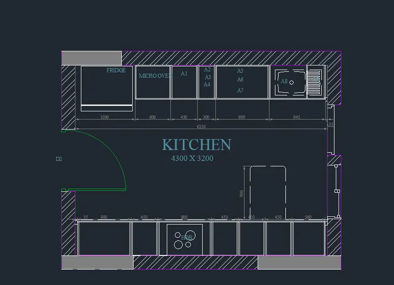
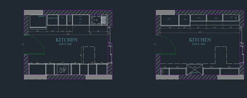
- The layout of the kitchen is shows the arrangement of the fridge, micro oven etc according to the facing walls of the kitchen space, with a corridor and a moving space between them.
- The column is the structural element that transmits through compression, the weight of the structure above to the other structural elements below. the column details consist of the reinforcement details and stirups details. it helps for site engineers for the arrangement of the column reinforcemnt and stirups.
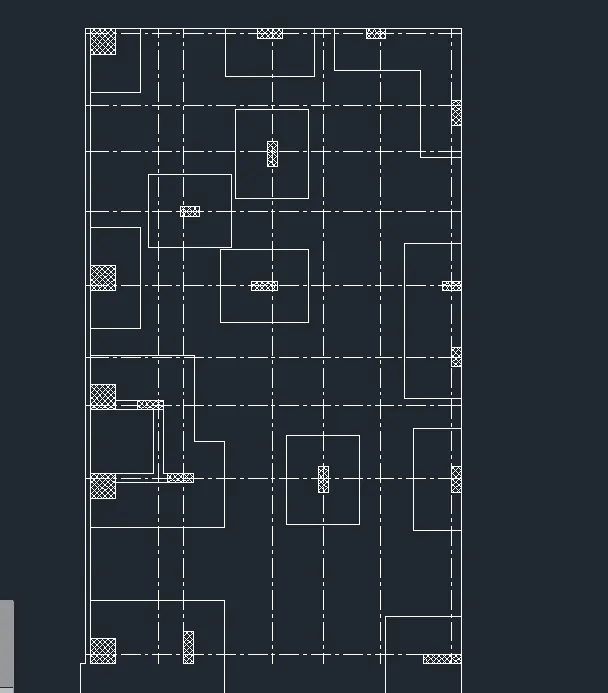
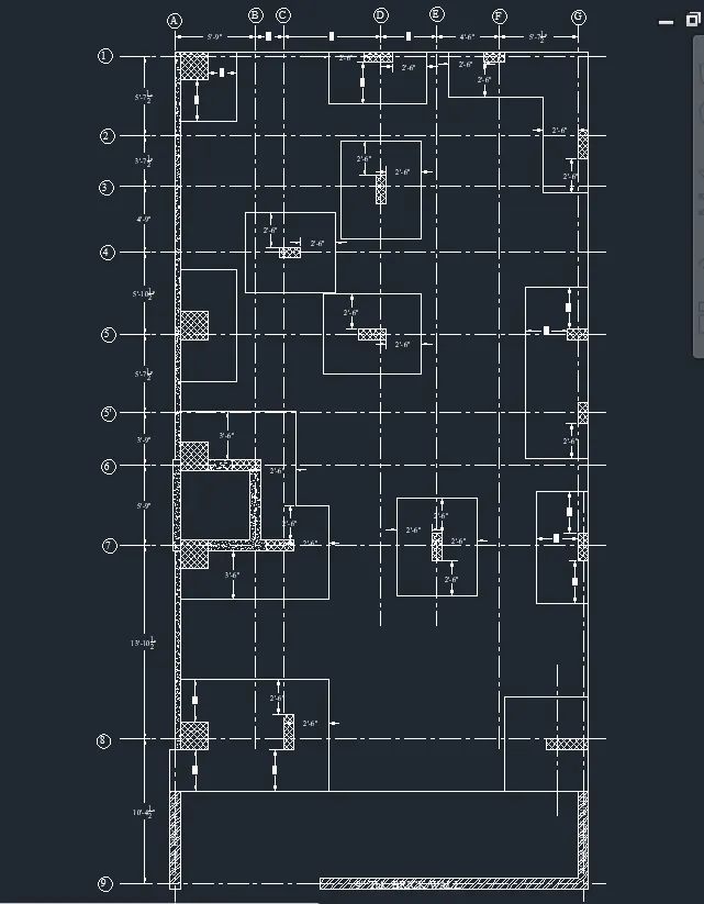
- The raft plan consist of the placement placement of the column and centre line details.
- The floor plan consist is the technical drawing showing the the view from the above the relationship between the rooms, spaces and other physical features at one level of the structure.
Commands used :
- Line command
- offset command
- Trim command
- Rectangle command
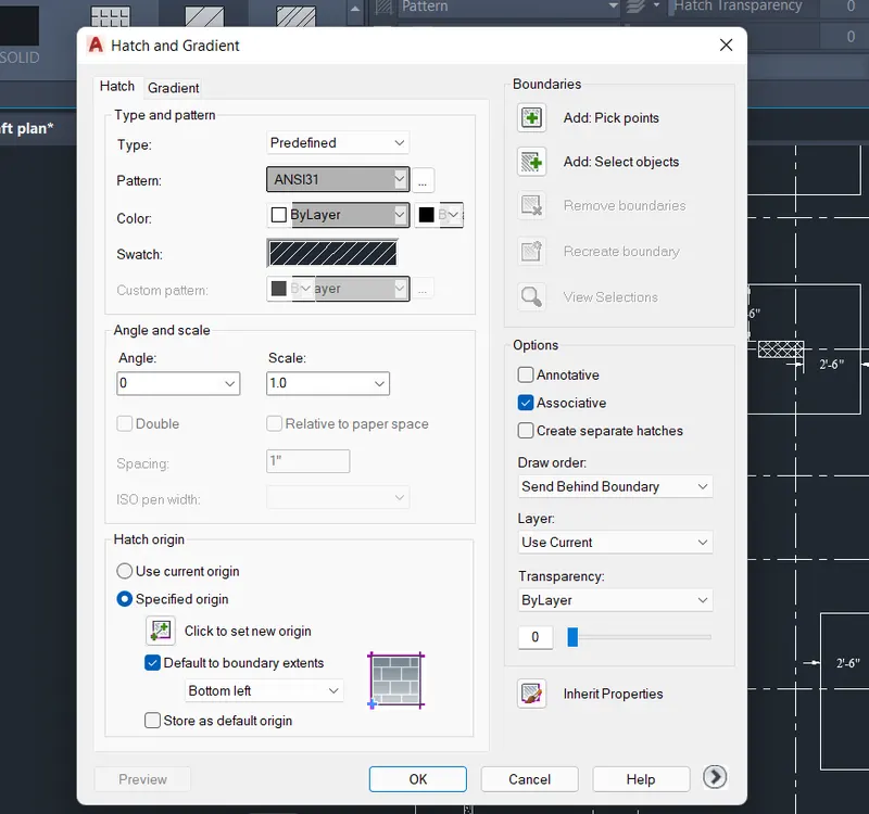
- Hatch command
- linear dimension command
- dim continue command
- limit command
- Un Command
- Xref command
- Xline command
- Dt command
- Leader command
- Block command
- Insert command
- block edit command
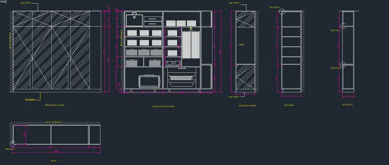
1. Elevation details of wardrobe
Step 1 :
- open the new sheet enter the UN select the decimal and by using the limit command enter the plot size of the sheet.
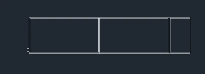
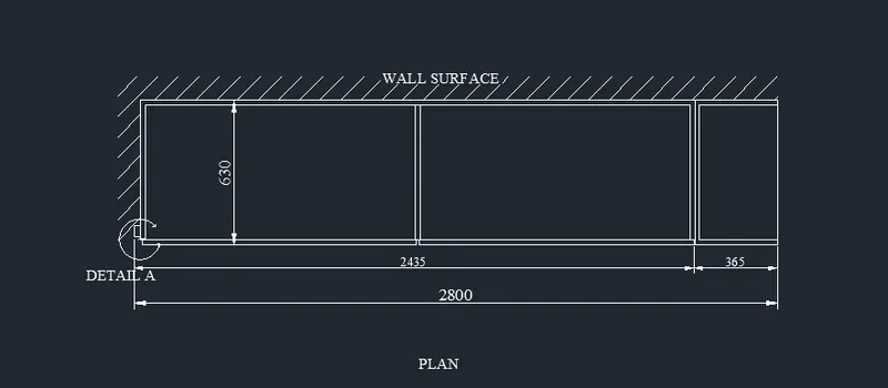
- Draw the rectangl;e of the size 2800 length and 630 mm width.
- Explode the rectangle.
- from left side give the of the distance of 1200, 1200 and 365
Step 2 :
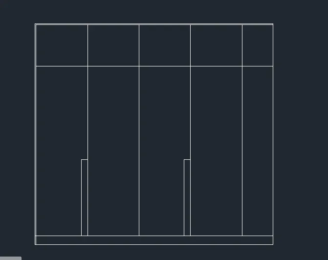
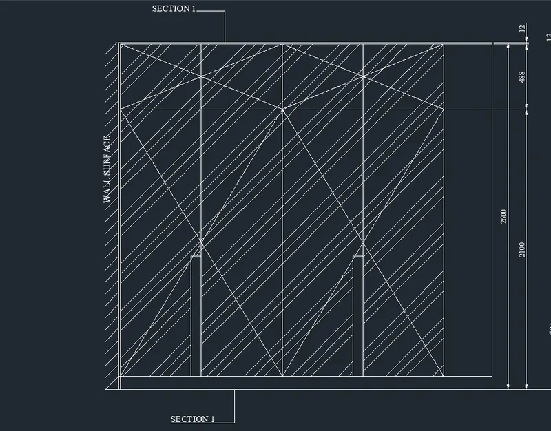
- Draw the rectangle of the size 2800 x 2600 and explode the rectangle.
- offset the bootoom line at a offset distance of 100, 2100 from the bottom length and last line is offset at ditance of 488.
- the offset the the vertical line at a ditance of 617mm, 607mm, 605mm, 607mm, 364mm ( distance is from last offset line).
- By using the linear dimension first dimension is given and used the continuous dimension all dimension are given.
- hatch is applied.
Step 3 :
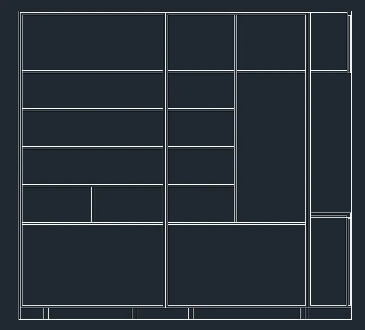
- Draw the rectangle of the size 2800 x 2600 and Explode the rectangle.
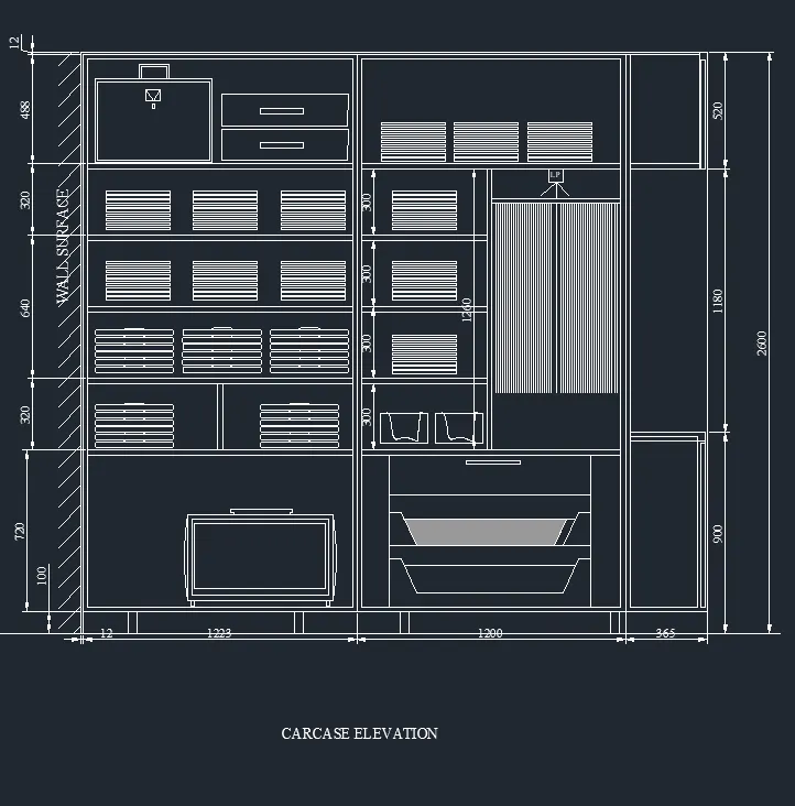
- Offset the bottom line by offset distance of 100mm, 720mm, 300mm, 640mm, 320mm, and 488mm. (length is with respect to the last offset line)
- offset the compartment line by 20mm below.
- offset the vertical line by 12, 1223, 1200 and 365 respectively.
- compartments are drawn by using the line command.
Step 4:
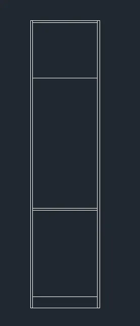
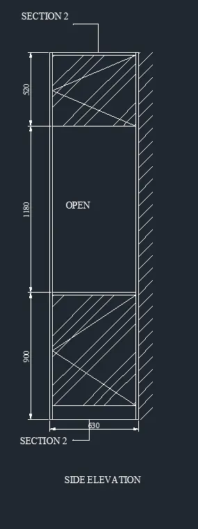
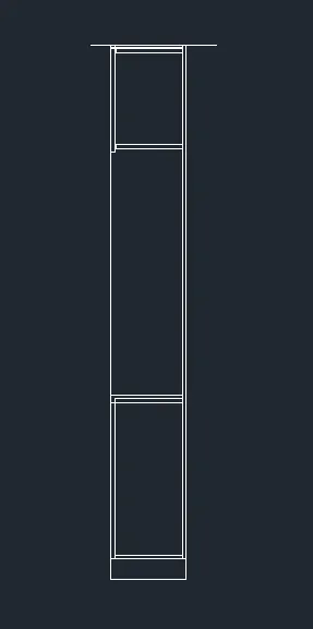
- draw the rectangle of the size 630 x 2600 and explode trhe rectangle.
- offset the bottom line at a distance of 900, 1180 and 520
- left side line and top line are offset inward at 12 mm
- hatch the below and top compartment.
- give the annotation.
Step 6 :
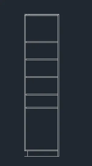
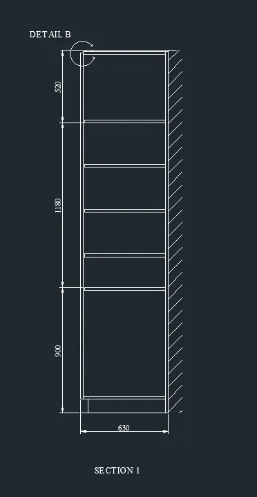
- draw the rectangle of the size 630 x 2600 and explode it.
- ooffset the below line at a offset dustance of 900, 1180 and 520 length is with respect to the last offset line.
Step 7:
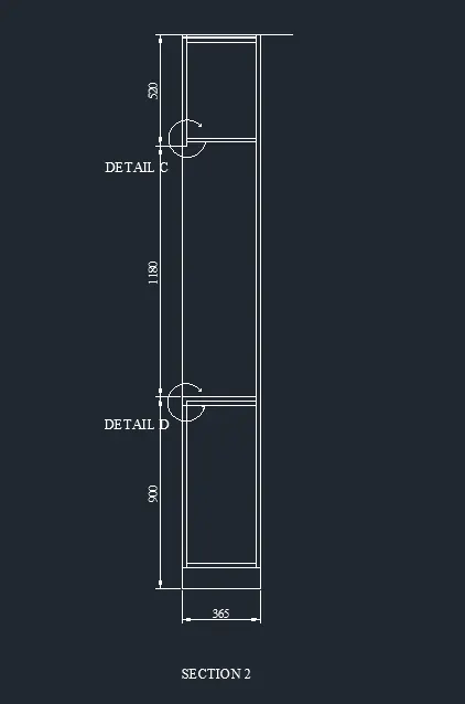
- Draw the rectangle of size 2600 x 365 and explode it.
- offset the below horizontal line 900, 1180 and 520 with respect to the last offset line.
- by using the dimlinear the dimension of the line is given.
2. Drawimg of the floor plan
- Open the new autocad file and set metric type the un in command promt and select the decimal
- by using the limits command give the limits of the drawing and zoom enter and select the All enter.
- use the xref command for reference drawing
- xref enter select the drawing to be imported give the scale and rotational angle as 0
- scle the pdf srawing into the required scale.
- Using the xline command draw horizontal and vertical lines.
- Consider the exterior wall as 230 mm and interior wall as 150mm
- offset the both hrozontal and vertical line by 230 mm
- offset the line by 9710, 230, 1650, 150, 4350 and 230 mm
- the line selected for the next offset is the the last offset line
- Trim the unwanted lines.
- offset the vertical offset line by 5310, 230, 2000, 230 and 2150 mm
- trim the unwanted lines. the unwanted lines.
- offset the below horizontal line of foyer by a 3220, 230 and 2100, 230, 2770,230 , 320, 230 and 4500 and 230mm
- trim the unwanted lines.
- offset the top right side vertical line by 1900 and 150 and join the top lines by a line command.
- trim the unwanted line
- offset the top right side line by a 1700,150, 2450, 150, 2100, 150mm respectively.
- Trim the unwanted lines.
- Trim the Door opening lines.
- Draw the windows
- Doors are drawn and it selected as a block and inserted where required by using the insert command.
- Text are given by using the single line text.
- The canopy is drawn as shown in the figure.
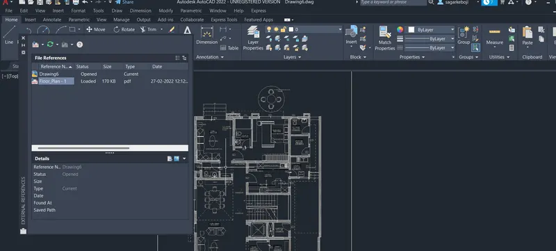
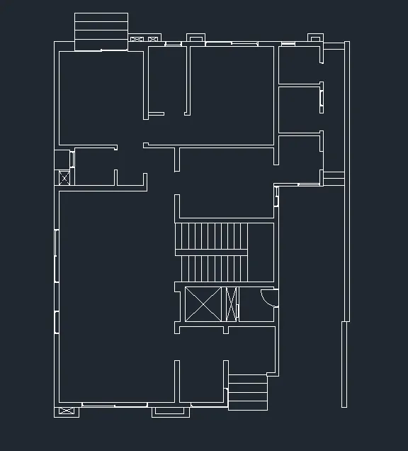
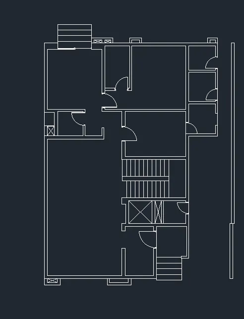
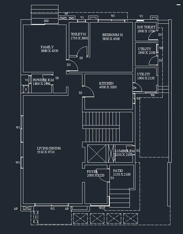
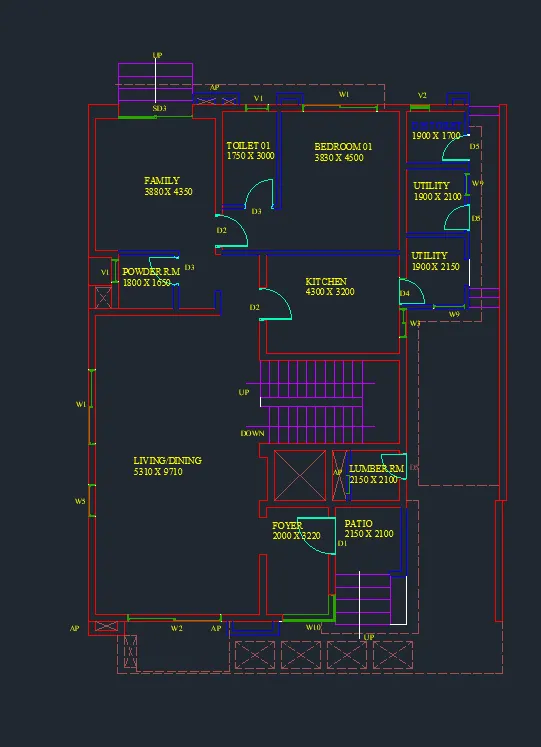
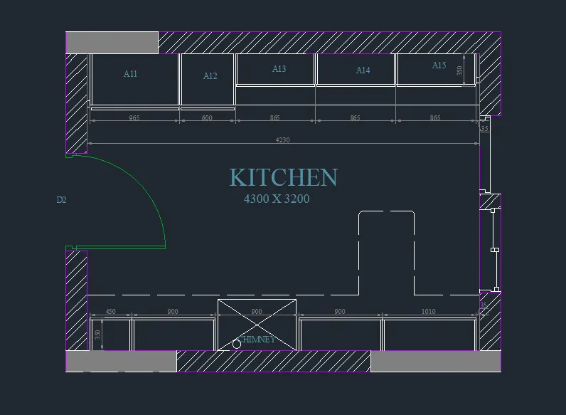
3. Kitchen Lyout
- Open the new autocad file and set metric type the un in command promt and select the decimal
- by using the limits command give the limits of the drawing and zoom enter and select the All enter.
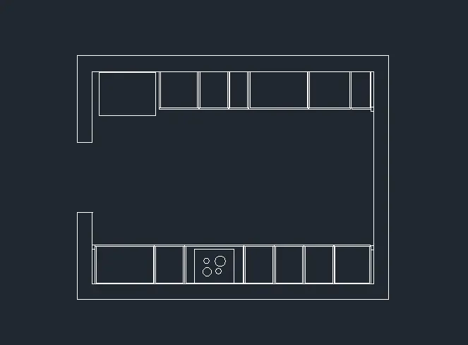
- Draw the rectangle of the size 4690 x 3660
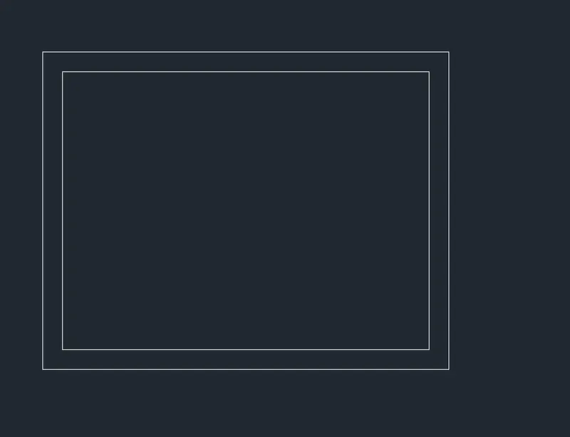
- From the left side draw the horizontal line 1300mm from the bottom
- offset this line with 1050mm offset distance.
- Trim the lines between the these two horizontal line.
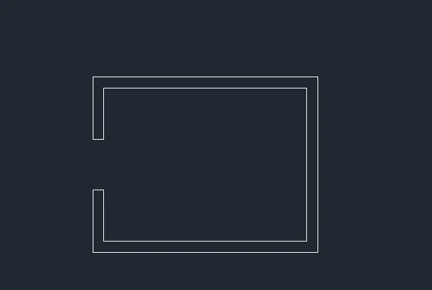
- Offset the horizaontal line of a distance of 560mm above and bottom line.
- from bottom vertical line offset in horizontal right side 35mm and trim the line above the offset the line
- offset the this vertical line by 900, 450, 900, 450, 450, 450, 560mmrtical
- from each line offset at distance of 20mm horizontal line below and vertical line by right and left side.
- trim the unwanted lines.
- From the top offset the vertical line by 100mm and trim the line below the 560mm offset line.
- offset this vertical line by 900, 600, 450, 300, 900, 945 mm
- from each line offset at distance of 20mm horizontal line upper and vertical line by right and left side.
- Trim the unwanted lkines.
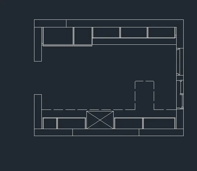
- Offset the horizaontal line of a distance of 350mm above and bottom line.
- from bottom vertical line offset in horizontal right side of 35mm and trim the line above the offset the line
- offset the this vertical line by 450, 900, 900, 900, 1010 mm.
- from each line offset at distance of 20mm horizontal line below and vertical line by right and left side.
- trim the unwanted lines.
- ffset the horizaontal line of a distance of 550mm above and bottom line.
- offset this vertical line by 35, 965, 600, 865, 865, 865 mm
- from each line offset at distance of 20mm horizontal line upper and vertical line by right and left side.
- From the top offset vertical line of distance 350mm.
- Trim the vertical lines crossing the 350mm line after A12
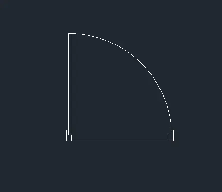
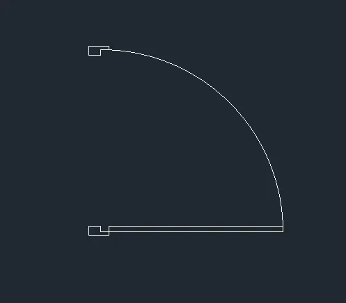
- The door is drawn as shown in the below figure.
- this doorb is converted as a block and it is inserted at required position.
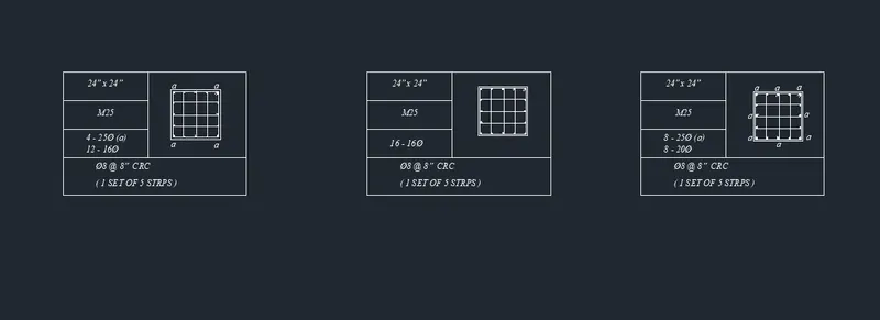
4. Column Details
- Open the new autocad file and set imperial and type UN in command promt select the engineering
- by using the limits command give the limits of the drawing and zoom enter and select the All enter.
- Draw the rectangle of the size by 24" x 24".
- Offset this rectangle by a offset distance of 0.8" inward.
- Explode the rectangle.
- internal rectangle is diveded into 4 segmens
- Select the donut of internal radius 0.1" and outer radius as a 1" placed at the every corner.
- Select the donar of internal diameter of 0.1" and outer diameter of 0.62" and placed as shown in the figure.
- erase the segments lines and join the line at surface of the donuts.
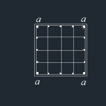
- Draw the rectangle of the size by 24" x 24".
- Offset this rectangle by a offset distance of 0.8" inward.
- Explode the rectangle.
- Internal rectangle is diveded into 4 segments
- Select the donar of internal diameter of 0.1" and outer diameter of 0.62" and placed as shown in the figure.
- Erase the segments lines and join the line at surface of the donuts as shown in the figure.
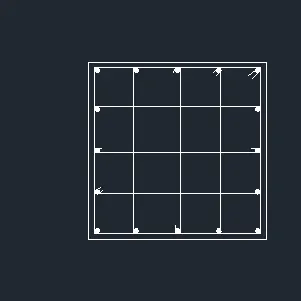
- Draw the rectangle of the size by 24" x 24".
- Offset this rectangle by a offset distance of 0.8" inward.
- Explode the rectangle
- Internal rectangle is diveded into 4 segments
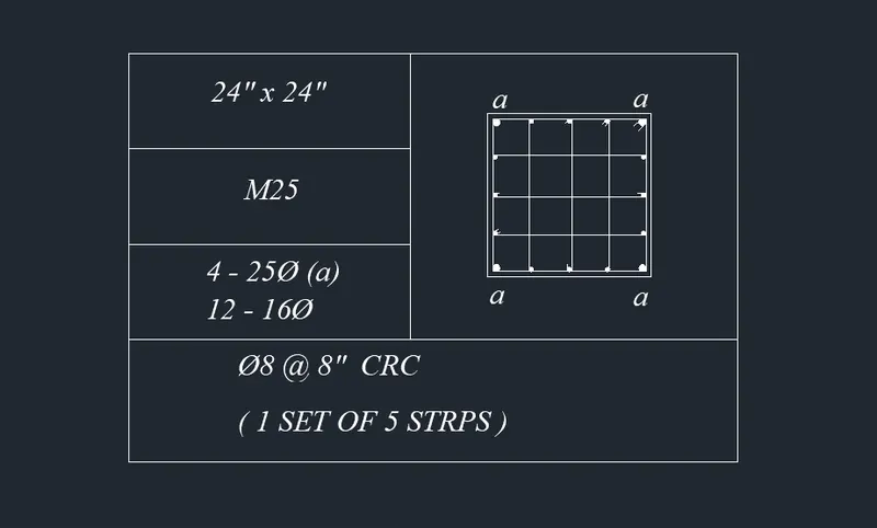
- Select the donar of internal diameter of 0.1" and outer diameter of 1" and placed as shown in the figure. as denoted as "a".
- Select the donar of internal diameter of 0.1" and outer diameter of 0.8" and placed as shown in the figure. other than the a
- Erase the segments lines and join the line at surface of the donuts as shown in the figure.
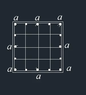
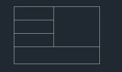
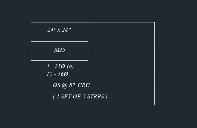
- Table is drawn by using the line command
- Single line text are written.
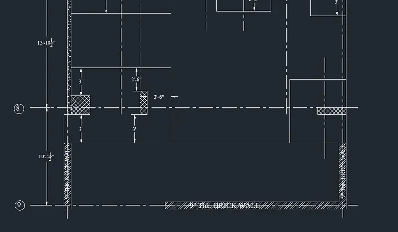
5. Raft Layout
- Open the new drawing by ctrl+N and and select the imperial and UN enter select the architectural.
- Using the limit command enter the plot size of the drawing.
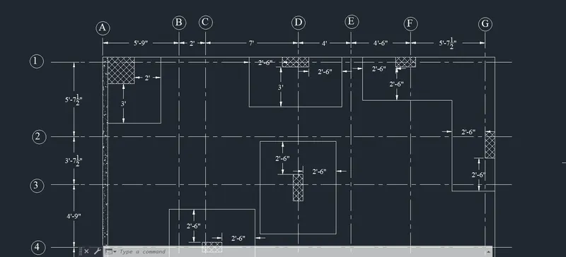
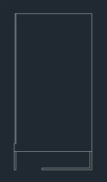
- Draw the recatangle of the size 29'7.5" x 53'
- Explode the rectangle.
- Offset the vertical line in left side by 5'9", 2', 7', 4', 4'6", 5'7.5"
- The offset distance is with respect to the last offset line.
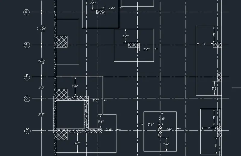
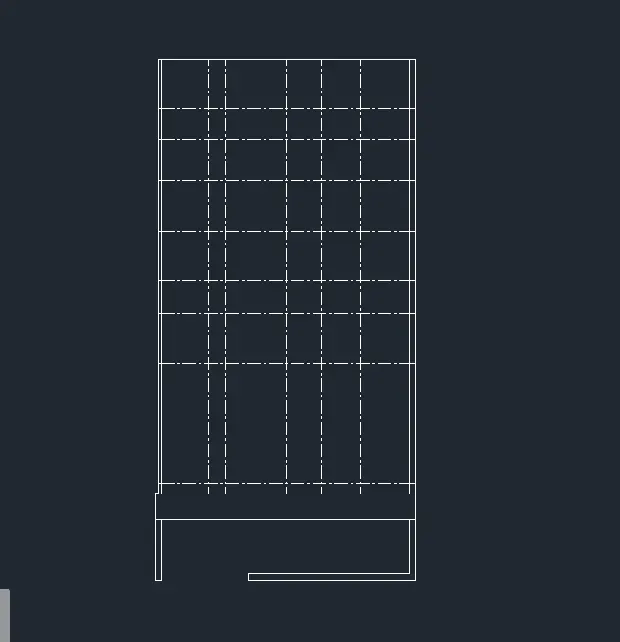
- Offset the horizontal line by offset distance of 5'7.5", 3'7.5", 4'9", 5'10.5", 5'7.5", 3'9", 5'9", 13'10.5" and 10'4.5"
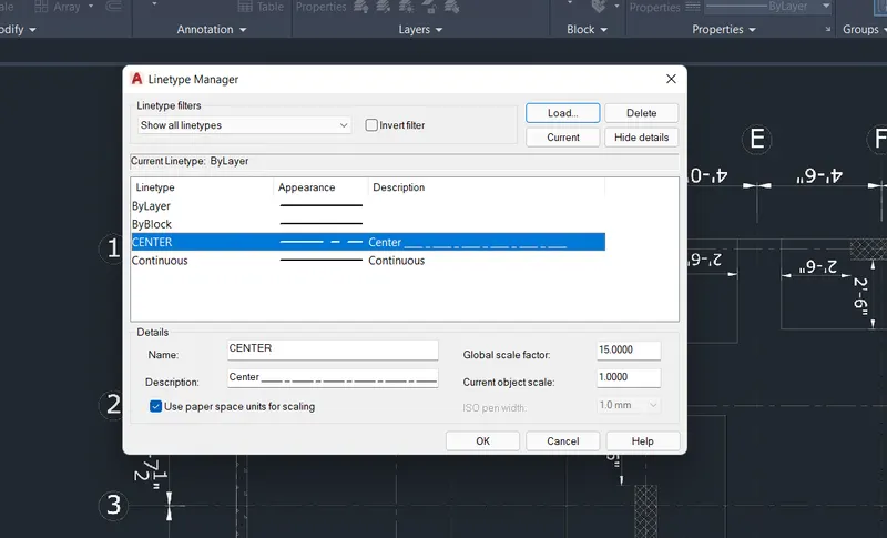
- These all offset lines are selected and these linetype changes to centre line.
- The bottom line is offset at a distance of 4.5" above and bottom of the centre line.
- by using the fille right vertcal line and outer line of the brick wall.
- From the left corner draw the rectangle of the size 2' x 2'
- Explode rectangle.
- the right side vertical line of the column is offset at a distance of 2'
- The bottom line of the column is offset at a distance of 3'
- Like this other column are drawn
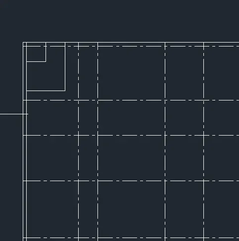
- The hatch is done for the columns and brick wall