Creating a Wardrobe detailed drawing, Floor Plan, Kitchen Layout and Column Detail using AutoCad
CREATING A WARDROBE DETAILED DRAWING, FLOOR PLAN, KITCHEN LAYOUT & COLUM DETAIL USING AUTOCAD
Jagadeep.M.M
1)Wardrobe:
AIM:
Draw the elevation & section of wardrobe.
PROCEDURE:
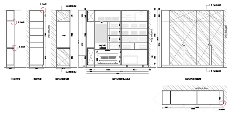
a)Carcase elevation:
Step 1:
- Open autocad softwere, type QNew incommand box,press enter.
- Select default setting as imperial setting.
- Drawing units setting as length=desimal,precision=0,Insertion scale=Millimeters, Ok
- Drawing limits setting as, specify the lower left corner=enter,upper right corner=4000,4000,enter.
- Type the command box Dimension style manager & press enter.
- enter modify-enter primary units-unit format=desimal, precision=0,enter Ok.
- Zoom command all-enter.
Step 2:
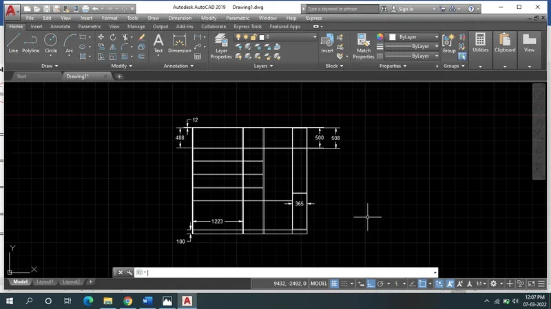
- In the commmand line type rectangle >2800*2600mm enter.
- In the command line type offset give the offset from top of the dimensions 12mm & 488mm.
- give the offset of below the line 300,600,900,1200,1888,press enter in command box.
- give the vertical offset of 548,1211,1200,365, press enter in command box.
- trim the unwanted lines in the trim command.
Step 3:
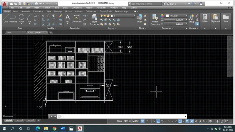
- in the command box give the hatch in the command box press enter.
- create the blocks in block command press enter.
Step 4:
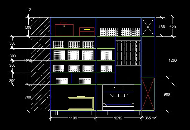
- give the dimension in the dimension command press enter.
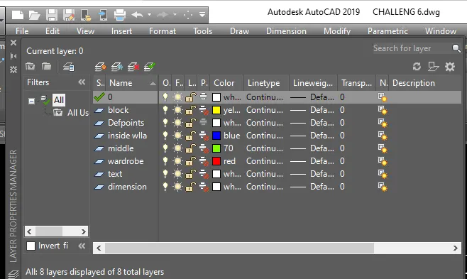
- give the layer in the layer command press enter.
b) Drawing of plan:
Step 1:
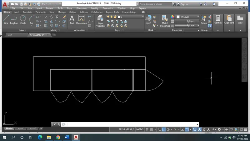
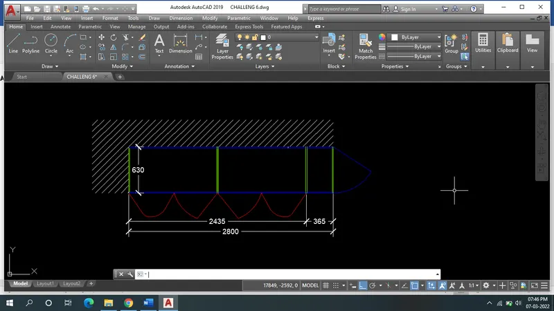
- Draw the rectangle size 2800*630mm using the rectangle command.
- give the offset of 12mm in offset command inside the thickness.
- expload the rectangle using explode command.
- using the offset command .take an offset of 365,1217,1217 .
- Draw the dooors by line & arc.
Step 2:
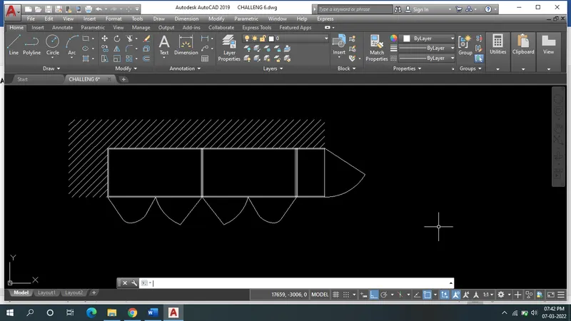
- in the command box give the hatch in the command box press enter.
- give the dimension in the dimension command press enter.
- give the layer in the layer command press enter.
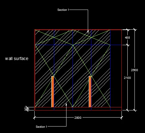
c)Drawing Front elevation:
Step 1:
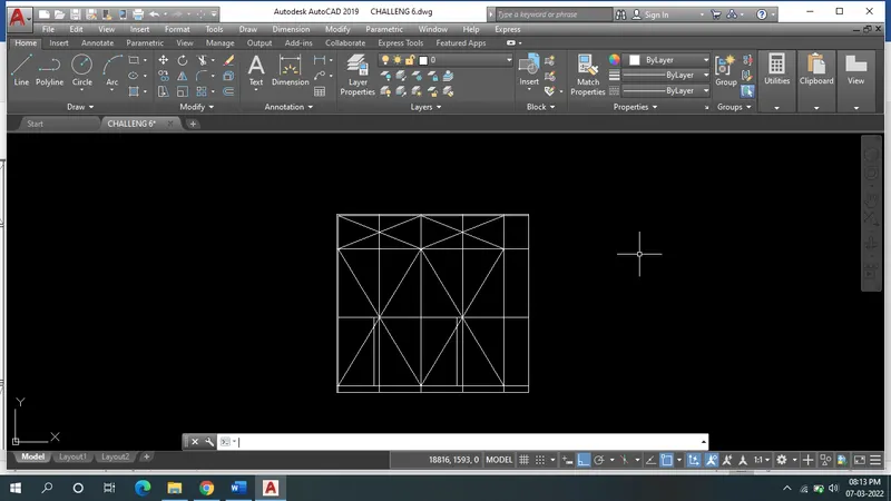
- Draw the rectangle of size 2800*2600mm using the rectangle command.
- using the offset command give the offset of 12mm inside the thickness.
- give the offset distance of vertical direction 605.75mm in 4 times & give the next offset 365mm enter.
- give the offset horizontal 100mm ,1100mm, 2100mm .bottom to above direction.
- trim the unwanted line using trim command.
Step 2:
- in the command box give the hatch in the command box press enter.
- give the dimension in the dimension command press enter.
- give the layer in the layer command press enter.
- using the text command to write the text.
d)Drawing side elevation:
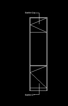
Step 1:
- Project the height from the carcase elevation.
- Draw a line of left side & offset 630mm from the right side.
- Take the offset of 20mm to show the thickness of side & top.
- Take the offset bottom to top as 100mm,90mm,20mm thickness, & 1180mm to show the divisions.
- Draw the section line 2-2.
- trim the unwanted lines.
Step 2:
- in the command box give the hatch in the command box press enter.
- give the dimension in the dimension command press enter.
- give the layer in the layer command press enter.
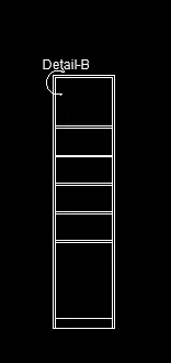
e) Drawing Section 1:
Step 1:
- As section-1 is i elevation project the height & width from the elevation.
- give the thickness of 20mm inside .
- For the inside cabinets project lines from the carcase elecation of 100mm,900m,300mm & 20mm thickness.
- trim the unwanted lines in trim command.
- Write the text in the tet command, Draw the arc,
Step 2:
- give the dimension in the dimension command press enter.
- give the layer in the layer command press enter.
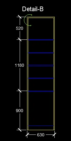
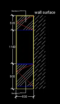
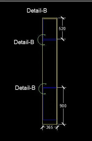
f) Drawing Section-2:
Step 1:
- Project the height from the side elevation as the section is taken from the side elevation.
- Give the offset of 365mm as width.
- Now give the offset on the side as well as top of 20mm.
- Project the 900mm line from bottom & 520mm line from the top.trim the unwanted lines in trim command.
- Write the text in the tet command, Draw the arc,
- give the dimension in the dimension command press enter.
- give the layer in the layer command press enter.
Layer properties:
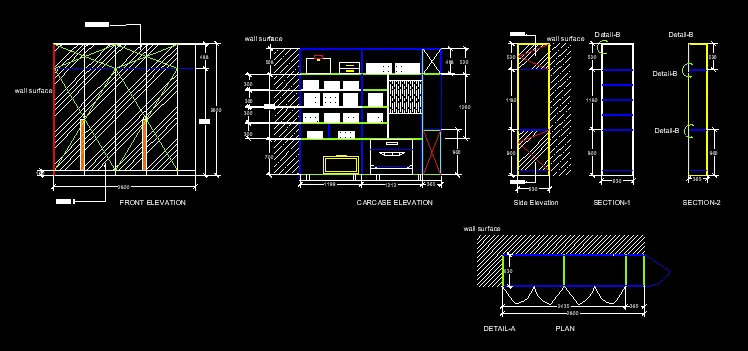
Cabinet Drawing:
Result:
2) Floor plan:
AIM:
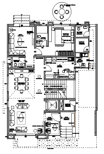
To draw the floor plan of building.
PROCEDURE:
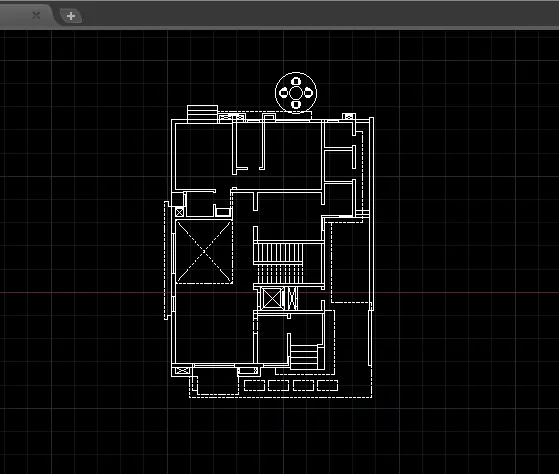
Step 1:
- Open autocad softwere, type QNew incommand box,press enter.
- Select default setting as imperial setting.
- Drawing units setting as length=desimal,precision=0,Insertion scale=Millimeters, Ok
- Drawing limits setting as, specify the lower left corner=enter,upper right corner=4000,4000,enter.
- Type the command box Dimension style manager & press enter.
- enter modify-enter primary units-unit format=desimal, precision=0,enter Ok.
- Zoom command all-enter.
Step 2:
- Draw the construction line using "XL-H" & XL-V".
- Give an offset of 230mm from the vertical to draw the thickness.
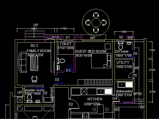
- First we draw the Drawing family room:
- Give an offset of 3880m from the wall thickness & offset of 230mm for the other side.
- Now draw the offset of 300mm as well as wall thickness from the horizontal construction line.
- Again draw the offset of 4350mm from the 300mm wall thickness for drawing the room.
- Now we draw the toilet:
- Give an offset of 1750mm from the right wall of family room & also offset 150mm to show wall thickness.
- Draw the offfset of 230mm from the horizontal construction line for the wall thickness of toilet on outside.
- Now draw an offset of 3000mm from the wall thikness so that toilet is formed.
- From the offseted line draw 150mm for the wall thickness inside.
- Now we draw the guest room:
- Draw the offset of toilet wall at a distance of 3830mm.
- Again offset the wall thickness 230mm.
- Offset 4500mm from the horizontal wall also offset 230mm from that line.
- Now we draw the DH toilet:
- Take n offset from the guest bedroom of distance 1900mm towards the right side.
- Now offset the wall thickness of 150mm from that line.
- Offset a distance of 1700mm from the horizontal line & walll thickness of 230mm.
- Also offset wall thickness of 150mm.
- Trim the extra line using trim tool.
- Now we draw the utility room:
- Take an offset of 2100mm downwards the wall of DH toilet.
- Also offset the wall thickness of 150mm.
- Now we draw the dishwasher utility:
- From the utility wall take an offset of 2150mm downwards & also the wall thickness of 150mm.
- Now we draw the kitchen:
- From the left wall of dishwasher utility room take an offset of 4300mm to the left & wall thickness of 230mm.
- From the wall guest bedroom draw an offset of 3200mm downwards & also wall thickness of 230mm.
- Now we draw the cupboard & powder room:
- From the extanded line give a distance of 1000mm for the cupboard & wall thickness of 150mm.
- Give an offset of 1800mm from the wall & wall thickness of 230mm.
- Make the above wall of powder room as 150mm.
- Take a offset of 1650mm from the wall to the bedroom.
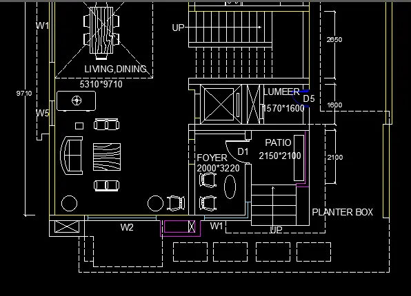
- Now we draw the living/dining:
- Draw an offset of 9710mm from the wall of powder room & also 230mm for the wall thickness.
- Now we draw the foyer:
- Draw an offset from the wall of living room 2000mm to the right & wall thickness of 230mm.
- Now we draw vrtical offset of 3220mm .
- offset of wall thickness is 150mm.
- Again offset 230mm for the lift wall & extand it to right.
- Now we draw patio:
- From the wall thickness of 230mm draw an offset of 2100mm downwards.
- From the wall of foyer draw an offset of 2150mm & wall thickness of 150mm on the right side.
- Now we draw lumber rooom:
- From the wall pation draw an offset of 1600mm toward backside.left side offset os 1570mm.
- Offset a wall thickness of 230mm & to the left side give an offset of 150mm as wall thickness.
- Now we draw duct & lift:
- Draw an offset of 500mm from the 150mm wall of lumber room & wall thickness of 230mm.
- Take an offset of 1620mm from the wall for left.
- Draw the side walls & front walls of 230mm.
- Now we draw stairs:
- Divide the stair room & offset 200mm to two sides by offset from the center line.
- We draw the first step then offset 300mm upto 11 divisions & rest portion forms landing & draw 10 theread on other side of division.
- Create ducts at front & backside:
- Assume the door,window & ventilators size.
- Create the outdoor seating:
- Draw a circle using circle command of radius 1398mm.
- Draw a circle using circle command of radius 452mm.
- draw the center line of the circle.
- draw the rectangle of length 400mm & width 200mm.
- Now draw an arc with start-center end with the endpoints & center of the length of the rectangle.
- Now give two offset of 50mm using offset command from the arc & join the end points of the offfseted acc.
- Draw another rectangle of length 100mm & width 50mm using rectangle command.
- Using the move command : select the base point & move to the required place.
- Using mirror command: mirror the chair to the opposit side by selecting base point.
- Using rotate command: rotate the chair & move it to the left side by selecting the base point.
- Again mirroring it to create the chair in the right side.
Step 3:
- Trim the unwanted line,using trim command.
- wherever line required draw the line.
Step 4:
- Draw the Door,Window,Ventilator as per assumed dimensions.
- give the text using text command & leader command
- give the dimension in the dimension command press enter.
- give the layer in the layer command press enter.
- Draw the blocks in design center command press enter.
Result:
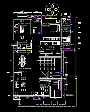
I WILL ATTACHED THE ANOTHER PDF RESULT FILE BELOW THE BROWSER OPTION
3)Kitchen layout:
AIM:
To draw the kitchen layout.
PROCEDURE:
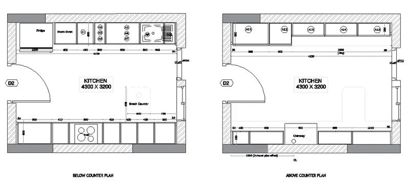
Step 1:
- Open autocad softwere, type QNew incommand box,press enter.
- Select default setting as imperial setting.
- Drawing units setting as length=desimal,precision=0,Insertion scale=Millimeters, Ok
- Drawing limits setting as, specify the lower left corner=enter,upper right corner=4000,4000,enter.
- Type the command box Dimension style manager & press enter.
- enter modify-enter primary units-unit format=desimal, precision=0,enter Ok.
- Zoom command all-enter.
Step 2:
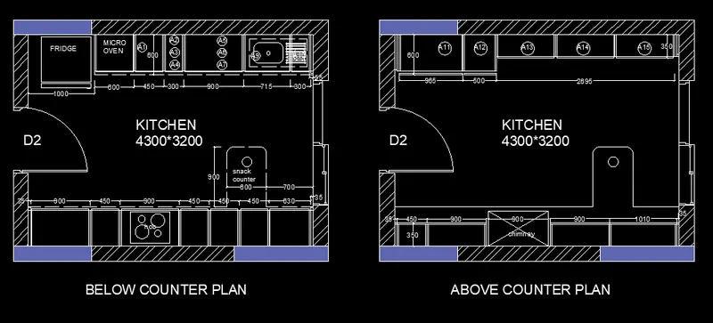
- Draw the below the counter plan:
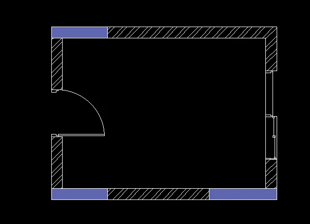
- We create the wall by drawing rectangle of 4300*3200mm & draw offset of 230mm as wall thickness.
- using the arc & line tio create the door,windows.
- In the command type the Hatch the drawing.
Step 3:
- In the command box type rectangle to draw the dimension of fridge.
- In the command box type offset & offset it to desireed distance to get the micro oven.
- use the trim command to remove the extra line.
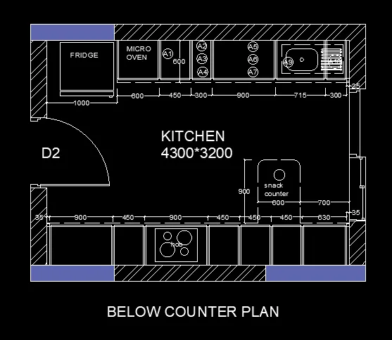
- Now type the offset in command box 1000,600,450,300,900,715,300,35mm hinge.
- give the offset of inside box 20mm.
- take the width of cabinet is 600mm.this is the above the dimensions.
- now draw the below the dimensions.
- Give the 35mm from the left & right side & create a hinge.
- Now type the offset command box give the offset 900,450,900,450,450,450,630mm enter.
- Draw the snack counter by giving offset distance 700mm from the left side of wall & 900mm from the 600mm width of cabinet & fillet with 10mm radius.
- type the dimension using dimension command.
- type the text using text command.
Step 4:
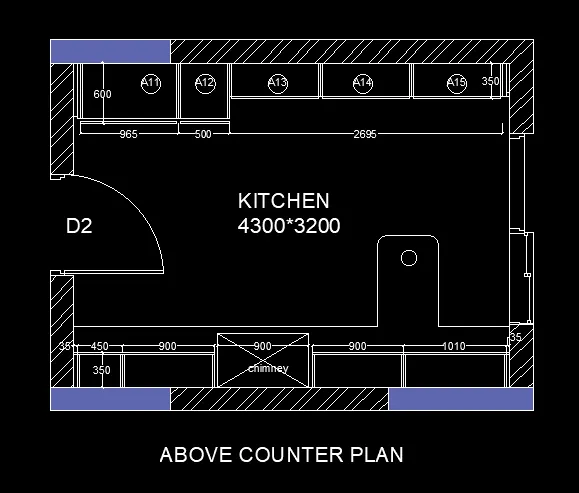
- Draw the Above the counter plan:
- We create the wall by drawing rectangle of 4300*3200mm & draw offset of 230mm as wall thickness.
- using the arc & line tio create the door,windows.
- In the command type the Hatch the drawing.
- In the command box type rectangle to draw the dimension of fridge.
- In the command box type offset & offset it to desireed distance to get the micro oven.
- use the trim command to remove the extra line.
- Now type the offset in command box 35,965,500,give the width of offset is 600mm.
- type the offset in command box give the offset of 2695mm & width is 350mm the 2695mm length divide the 2 segment & join the line.
- give the offset of inside box 20mm.
- now draw the below the dimensions.
- Give the 35mm from the left & right side & create a hinge.
- Now type the offset command box give the offset 450,900,35,900,35,900,1010,35mm enter.
- the chimney width will be 528mm & remaining cabinet willl be 350mm.
- Draw the snack counter by giving offset distance 700mm from the left side of wall & 900mm from the 600mm width of cabinet & fillet with 10mm radius.
- type the dimension using dimension command.
- type the text using text command.
Result:
4)Column details:
AIM:
To draw the Column details.
PROCEDURE:
Step 1:
- Open autocad softwere, type QNew incommand box,press enter.
- Select default setting as imperial setting.
- Drawing units setting as length=(Engineering),precision=0'0.0", Ok
- Drawing limits setting as, specify the lower left corner=enter,upper right corner=100',100',enter.
- Type the command box Dimension style manager & press enter.
- enter modify-enter primary units-unit format=Engineering, precision=0'0.0",enter Ok.
- Zoom all type the command box press enter.
Step 2:
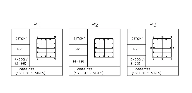
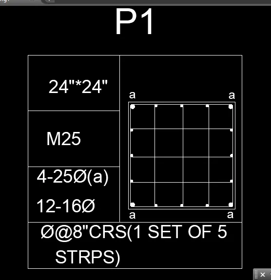
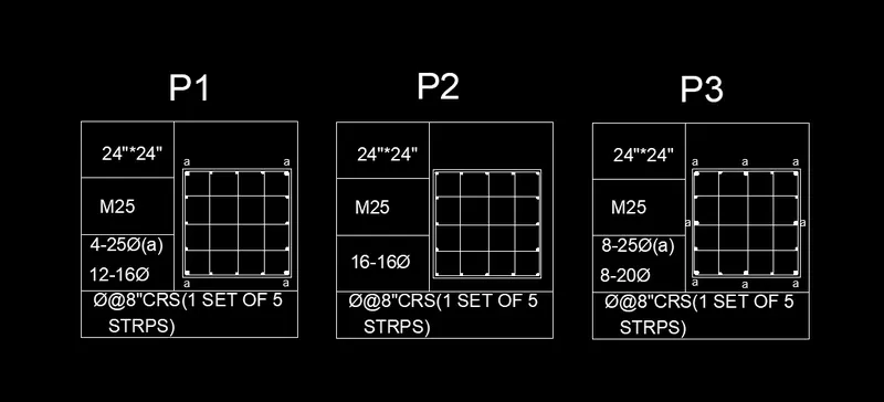
a) For column P1 size of 24"*24" having 4 number of 25mm dia & 12number of 16mm dia
- Now we draw the rectangle of size 24"*24" using rectangle command.
- By using offset command give the offset of 0.5" cover of concret.
- Explode the inner rectangle.
- now using the circle command:select the tan tan radius circle & give the radius odf 0.5".
- as the four corners are having 25mm dia bar mirror the circle in both the direction.
- Using the divide command divide the left line into 4 segment & type "DDPTYPE" to make the point visible.
- Now create the circle with center radius as 0.31" & place the side of the circle in the center of the point.
- Copy the two circle & place it in the position of the point.
- Now mirror the 16mm dia bars vertical & horizontal direction.
- connect the bars by 8mm stirrups by using the command.
- Now we fill the circle in the hatch command.
- Mark "a" for in between reinforcement to indicate it as 25mm dia.
- Create the column to indicate the size of column, grade of concrete & reinforcement details using multiline text with text height as 2" & text style as txt.shx.
Step 3:
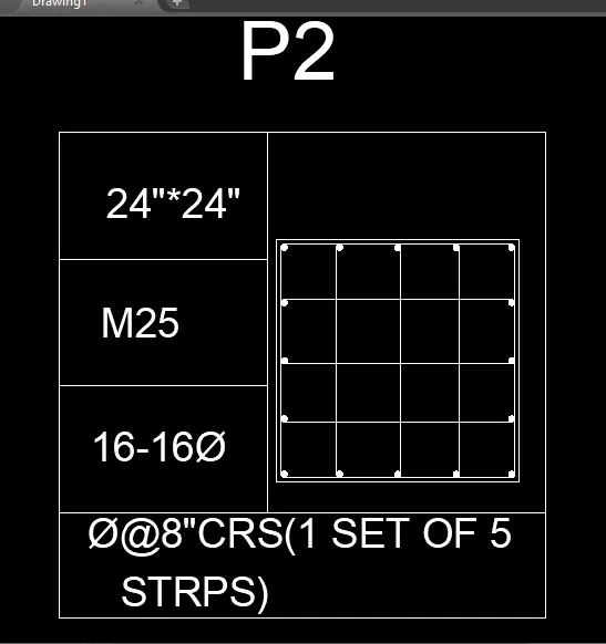
b)For column P2 size of 24"*24" having 16 number of 16mm dia
- Now we draw the rectangle of size 24"*24" using rectangle command.
- By using offset command give the offset of 0.5" cover of concret.
- Explode the inner rectangle.
- now using the circle command:select the tan tan radius circle & give the radius odf 0.31".
- as the four corners are having 16mm dia bar mirror the circle in both the direction.
- Using the divide command divide the left & top line into 4 segment & type "DDPTYPE" to make the point visible.
- Now mirror the 16mm dia bars vertical & horizontal direction.
- connect the bars by 8mm stirrups by using the command.
- Now we fill the circle in the hatch command.
- Create the column to indicate the size of column, grade of concrete & reinforcement details using multiline text with text height as 2" & text style as txt.shx.
Step 4:
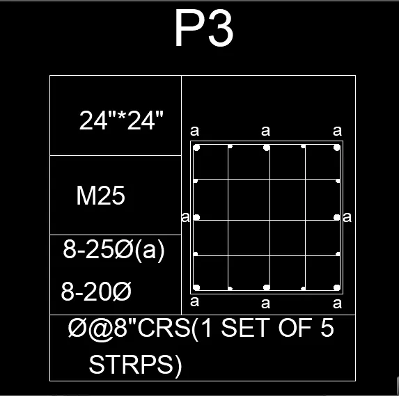
c)For column P3 size of 24"*24" having 4 number of 25mm dia & 8number of 20mm dia
- Now we draw the rectangle of size 24"*24" using rectangle command.
- By using offset command give the offset of 0.5" cover of concret.
- Explode the inner rectangle.
- now using the circle command:select the tan tan radius circle & give the radius odf 0.5".
- as the four corners are having 25mm dia bar mirror the circle in both the direction.
- Using the divide command divide the left & top of line into 4 segment & type "DDPTYPE" to make the point visible.
- Now create the circle with center radius as 0.39" & place the side of the circle in the center of the point.
- Copy the two circle & place it in the position of the point.
- Now mirror the 20mm dia bars vertical & horizontal direction.
- connect the bars by 8mm stirrups by using the command.
- Now we fill the circle in the hatch command.
- Mark "a" for in between reinforcement to indicate it as 25mm dia.
- Create the column to indicate the size of column, grade of concrete & reinforcement details using multiline text with text height as 2" & text style as txt.shx.
Result:
5)Raft Layout:
AIM:
To draw the Raft layout.
PROCEDURE:
Step 1:
- Open autocad softwere, type QNew incommand box,press enter.
- Select default setting as imperial setting.
- Drawing units setting as length=(Engineering),precision=0'0.0", Ok
- Drawing limits setting as, specify the lower left corner=enter,upper right corner=100',100',enter.
- Type the command box Dimension style manager & press enter.
- enter modify-enter primary units-unit format=Engineering, precision=0'0.0",enter Ok.
- Zoom all type the command box press enter.
Step 2:
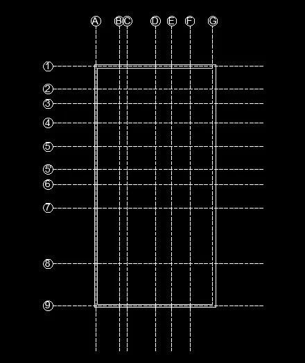
- Draw the vertical construction line using command XL-V.
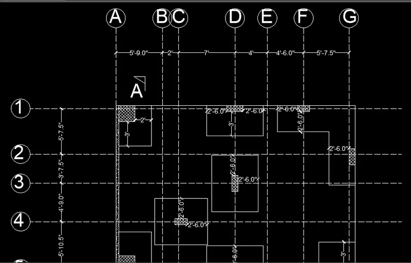
- Offset of the vertical distance is 5'9", 2', 7', 4', 4'6", 5'7.5".
- Draw the Horizontal construction line using command XL-X.
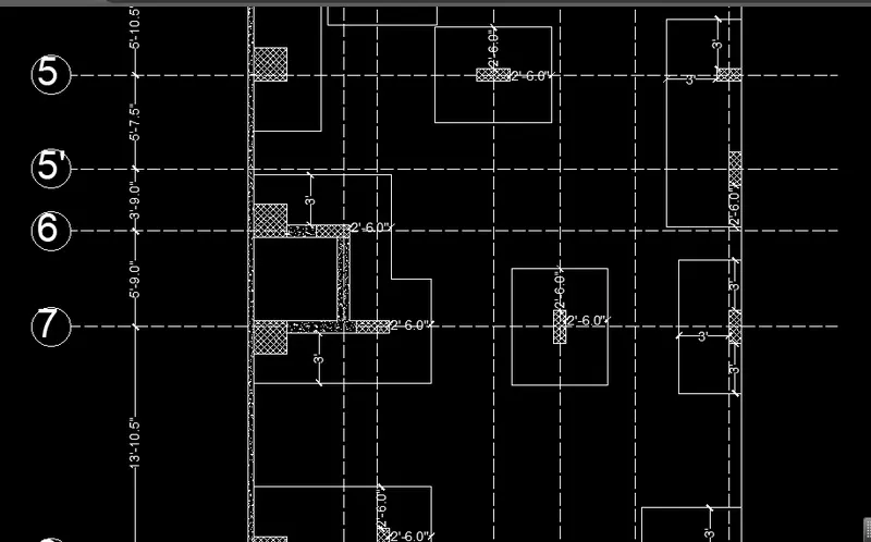
- Offset of the horizontal distance is 5'7.5", 3'7.5", 4'9", 5'10.5", 5'7.5", 3'9", 5'9", 13'10.5",10'4.5".
- Chang the line type to ISO dash by chicking the line property.
- Mark horizontal lines from 1 to 9.
- Vertical lines from A to G.
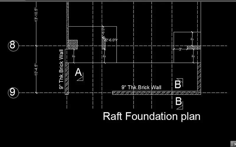
- Draw the bottom thickness of wall as 9" with the grid line at center.
- A thickness of 4.5" is drawn from the grid line inside the left vertical grid line.
Step 3:
a)Column between grid line A&B & 1&2 of column size 24"*24".
- Draw a rectangle of 2'*2' by rectangle command & place it in required position.
- Explode it.
- offset 2' vertical & 3' horizontal from the column.
- join the line using fillet command.
- hatch the column using hatch command.
b)Column between grid line C&E & 1&2 of column size 24"*9".
- Draw a rectangle of 2'*9" by rectangle command & place it in required position.
- Explode it.
- offset 2'6" vertical & 3' horizontal from the column.
- join the line using fillet command.
- hatch the column using hatch command.
c)Column between grid line C&E & 1&2 & F&G & 2&3of column size 9"*18" & 9"*24".
- Draw a rectangle of 18"*9" by rectangle command & place it in required position.
- Explode it.
- offset 2'6" vertical & 2'6" horizontal from the column.
- join the line using fillet command.
- hatch the column using hatch command.
- Draw a rectangle of 9"*24" by rectangle command & place it in required position.
- Explode it.
- offset 2'6" vertical & 2'6" horizontal from the column.
- join the line using fillet command.
- hatch the column using hatch command.
d)Column between grid line C&E & 2&4 of column size 24"*9".
- Draw a rectangle of 2'*9" by rectangle command & place it in required position.
- Explode it.
- offset 2'6" on all side.
- join the line using fillet command.
- hatch the column using hatch command.
e)Column between grid line A&D & 1&5 of column size 9"*18".
- Draw a rectangle of 9"*18" by rectangle command & place it in required position.
- Explode it.
- offset 2'6" on all side.
- join the line using fillet command.
- hatch the column using hatch command.
f)Column between grid line A&B & 4&5 of column size 24"*24".
- Draw a rectangle of 24"*24" by rectangle command & place it in required position.
- Explode it.
- offset 3' on the left & right side & 2' toward front.
- join the line using fillet command.
- hatch the column using hatch command.
g)Column between grid line C&E & 4&5' of column size 9"*24".
- Draw a rectangle of 9"*24" by rectangle command & place it in required position.
- Explode it.
- offset 2'6" on all sides.
- join the line using fillet command.
- hatch the column using hatch command.
h)Column between grid line F&G & 4&6 of column size 9"*18".
- Draw a rectangle of 9"*18" by rectangle command & place it in required position.
- Explode it.
- offset 3'on one side & 3'toward front sides.
- join the line using fillet command.
- hatch the column using hatch command.
- Draw a rectangle of 9"*18" by rectangle command & place it in required position.
- Explode it.
- offset 2'6" on one side & 3' toward front sides.
- join the line using fillet command.
- hatch the column using hatch command.
i)Column between grid line F&G & 6&8 of column size 24"*9".
- Draw a rectangle of 9"*24" by rectangle command & place it in required position.
- Explode it.
- offset 3' two side & 3' toward front side.
- join the line using fillet command.
- hatch the column using hatch command.
j)Column between grid line A&D & 5&8 of column size 9"*24" & 24"*24".
- Draw a rectangle of 9"*24" by rectangle command & place it in required position.
- Explode it.
- offset 2'6" to the front from the wall & column.
- Give the offset 3' to the right & left side.
- join the line using fillet command.
- hatch the column using hatch command.
- Draw a rectangle of 24"*24" by rectangle command & place it in required position.
- Draw a 9" thickness wall from the column at a distance of 3'9".
- Explode it.
- offset 3' on one side & 3' toward front.
- join the line using fillet command.
- hatch the column using hatch command.
k)Column between grid line A&D & 5&8 of column size 24"*24" & 9"*2'6"
- Draw a rectangle of 24"*24" by rectangle command & place it in required position.
- Explode it 7 extand the base of rectangle from grid point C offset 4.5" & create a rectangle of 9"*2'6"
- offset 2'6" to the front from the wall & column.
- Give the offset 2"6" to the front & left of the 9"*2'6" & offset 0f 3' from the 2'*2' rectangle.
- join the line using fillet command.
- hatch the column using hatch command.
l)Column between grid line F&G & 8&9 of column size 3'*9".
- Draw a rectangle by selecting base point as intersection of 4.5"& wall & giving dimensions as 3' & 9".
- Delete the offset line.
- give the offset with a distance of 3'.
- join the line using fillet command.
- hatch the column using hatch command.
- Now we insert the text using multiline text with height 15".
- Dimension is done by dimension tool & measure the all distance between grid lines & other required distance.
- Create the layer & assign the different colours to each layer.
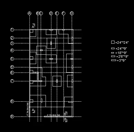
Result:
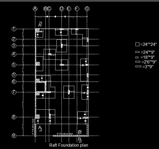
I WILL ATTACHED THE ANOTHER PDF RESULT FILE BELOW THE BROWSER OPTION