Creating a Wardrobe detailed drawing, Floor Plan, Kitchen Layout and Column Detail using AutoCad
1.
AIM:
To sketch the wardrobe Plan, Front Elevation, Section 1, Side elevation, and Section 2 using the AutoCAD software, and explain the detailed procedure step by step to obtain the result.
INTRODUCTION:
AutoCAD is a computer aided design software and drafting software application.
In this project, i have used various commands like,
* Line, Line(transparency 50), Polyline, Circle, Arc - to create the plan and section.
* Hatch and Hatch with transparency 50 - to create wall surface and in front elevation.
* Dtext, Multi-leader - to mention the texts.
* Commands DIM Linear, DIM Continue - to create the Dimension lines
* Copy (Array) - to create objects in the section 1 diagram.
* LAYERS - created individual layers for Plan and Sections, Hatch, objects, Dimensions, and texts.
* Fillet, Trim/erase, Offset, trim, ED - are regularly used at various places to complete the diagrams.
In the next step, the procedure is explained perfectly.
PROCEDURE:
- Open AutoCAD software
- Start from scratch
- Set the units to decimal and select ok
- Set limits as lower left corner (0,0) and upper right corner (1000,1000)
- Import the drawing pdf to AutoCAD to check the dimensions and start the drawing as per the given data.
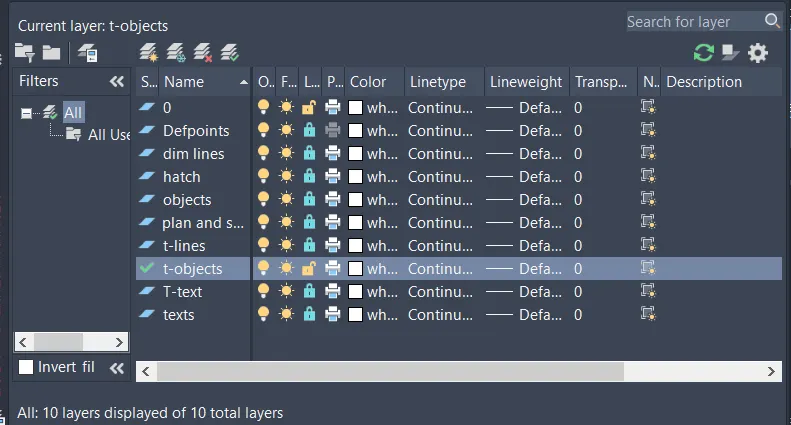
- Go to layer properties < create new layers < name the layers for reference < close
- Choose the Layer [plan and sections]
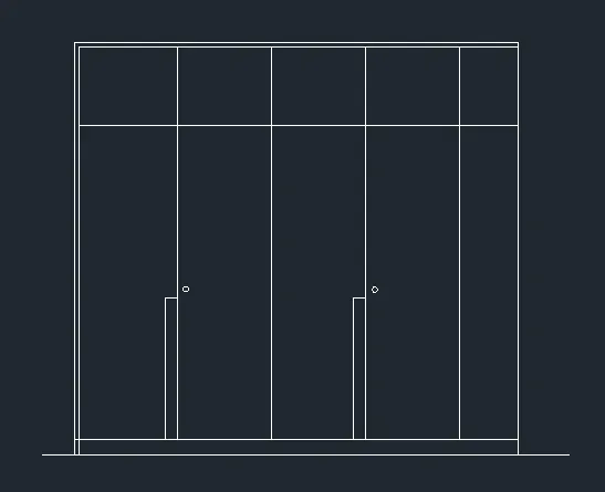
- Using the commands line, polyline, offset, fillet, trim and circle, the wardrobe outline is drawn.
- Choose the layer [T-lines]
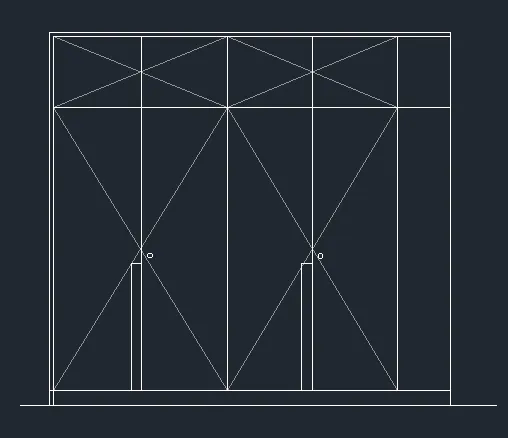
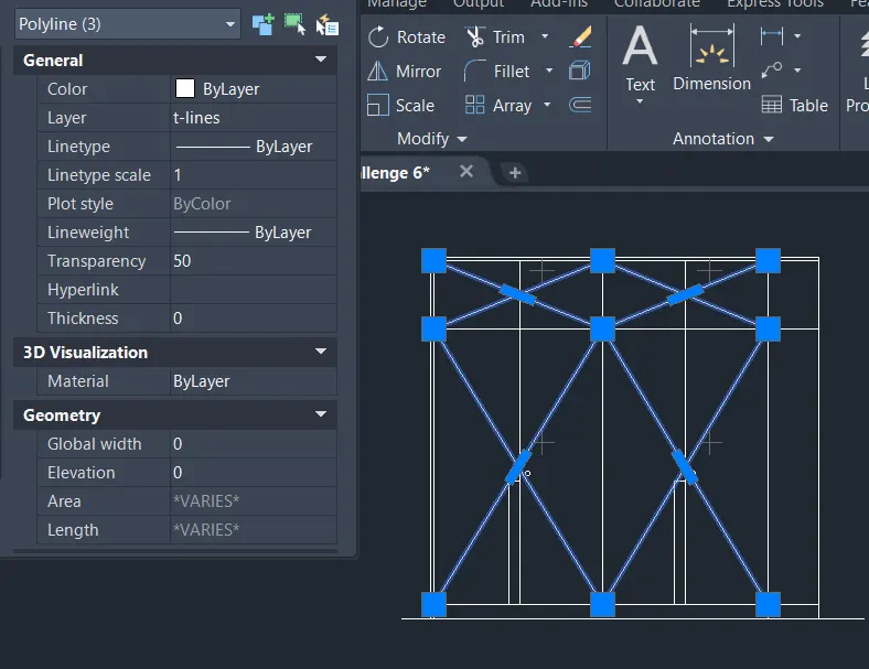
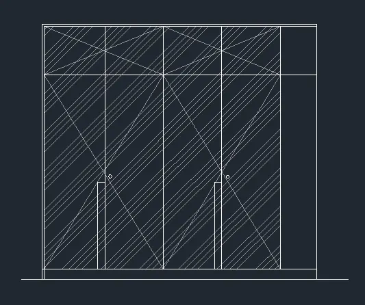
- The polylines are drawn connecting all the corners inside and the transparency of the line is reduced to 50.
- Choose the Layer [Hatch]
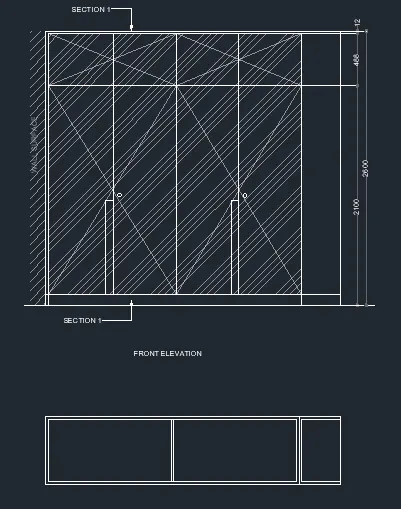
- Go to < Hatch command < choose ANSI34 < Reduce hatch transparency to 50 < Increase the scale to 15 < choose the wardrobe area < enter.

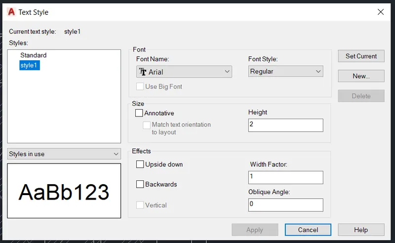
- Go to < Text style manager < create new style 1 < font name Arial < height 2 < apply < set current < close.
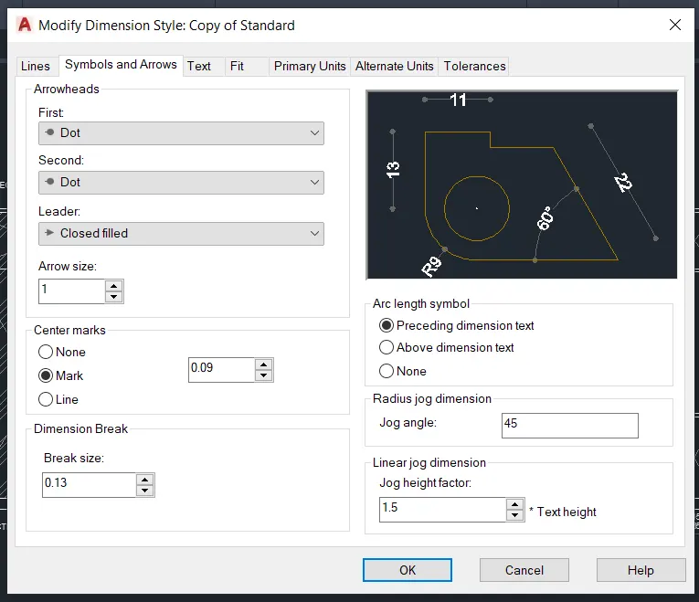
- Go to < manage dimension styles < select symbols and arrows < choose arrowheads as Dots < make arrow size as 1 < ok
- Choose the Layer [texts]
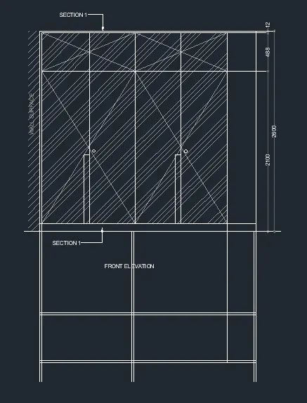
- Using DText command , the text FRONT ELEVATION is mentioned in the bottom.
- Using Multi-leader command , the text SECTION 1 is mentioned.
- Create a reference area to the total height on the left side of the wardrobe to mention the wall surface.
Choose the Layer [Hatch]
- Using Hatch command < choose ANSI31 < Reduce hatch transparency to 50 < Increase the scale to 15 < select the reference area < enter.
- After the hatch is created delete the reference lines.
- Choose the Layer [T-texts]
- Using Dtext command < change the angle to 90' < mention the text WALL SURFACE in the hatch area.
- Choose the Layer [ Dim lines]
- Using the commands - Dim linear , Dim continue, ED (text edit). The dimensions are marked for the diagram.
- Choose the Layer [plan and sections]
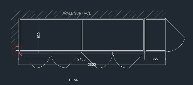
- The wardrobe outer lines are extended down to create a plan of the wardrobe.
- Using the command lines, polyline, hatch, arc, circle, dim linear, dtext, trim, edit-text, and transparency, the plan is drawn perfectly.
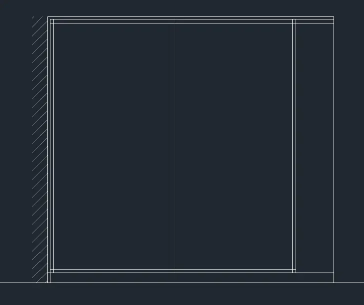
- Using copy command, select all the outer lines of the wardrobe plan, wall hatch and paste it parallel to the front elevation.
- Using the commands line, copy-(array), offset and trim, the internal shelves are drawn.
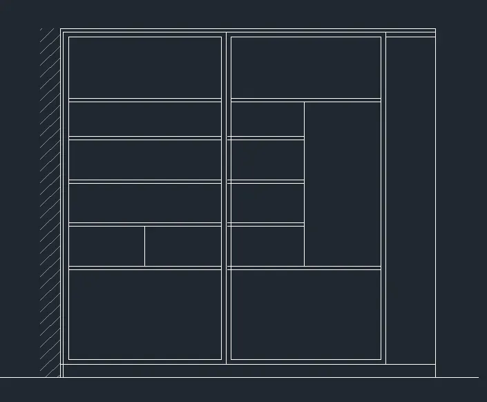
- To create multiple objects, first i have completed one object and then using copy command < select objects < specify base point < choose array and enter the number of items as 6 < choose fit and place the copy of objects as per the spacing available or input the standard distance in fit < enter.
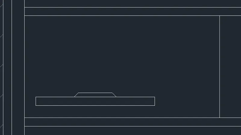
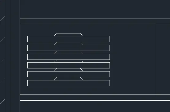
- Create different objects and repeat the previous step of copy-(array) command to create multiple objects.
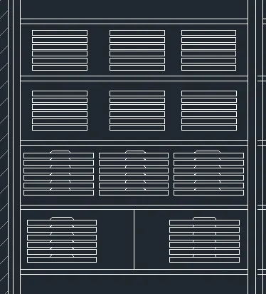
- Using the commands polyline, offset, trim, and copy, the following briefcase and other two objects are created.

- Using the command line, a long rectangle like boundary and hanger like structure is created in the top.
- Go to < Hatch command < choose lines < change angle to 90' < increase the scale to 5 < select the area < enter.
- Erase the boundary lines after hatching is completed.
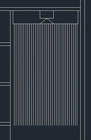
- Using the commands, polyline, offset, line, arc, and trim the following object is created.
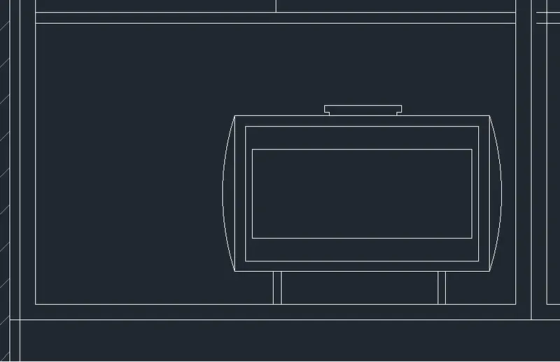
- First, i have created the objects using the commands line, offset and polyline.
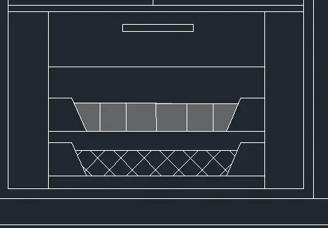
- Then using the < Hatch command < choose ANSI37 for the bottom object and enter < And Solid Hatch for the center object and enter.
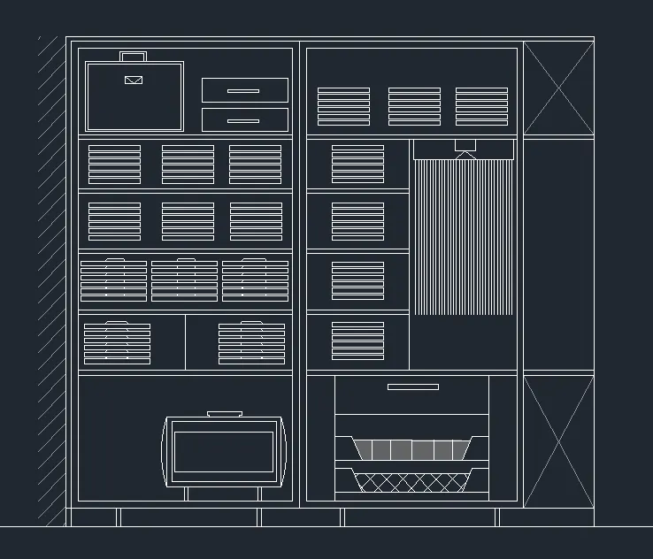
- The following picture is the completed diagram of wardrobe section before the dimensions and texts inputs.
- Again, using the same commands like line, polyline, transparent line (transparency 50), offset, fillet, Hatch, Circle and trim/erase, the following three diagrams of side elevation, section 1 and section 2 are drawn.
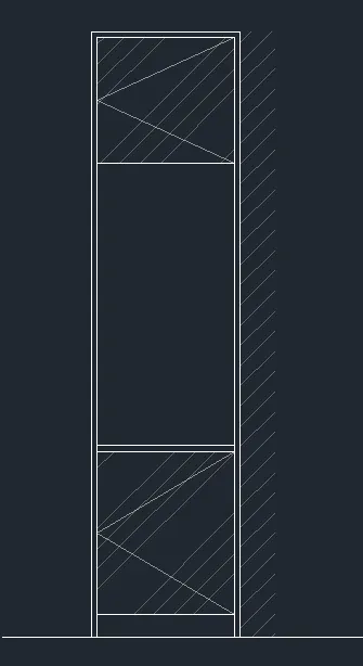
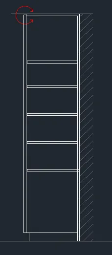
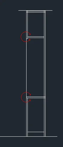
- The following picture shows the completion of all diagrams before the dimension and text inputs are given except the front elevation and plan because it is mentioned there to create the required layers for the diagram.
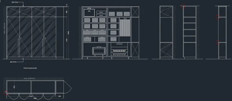
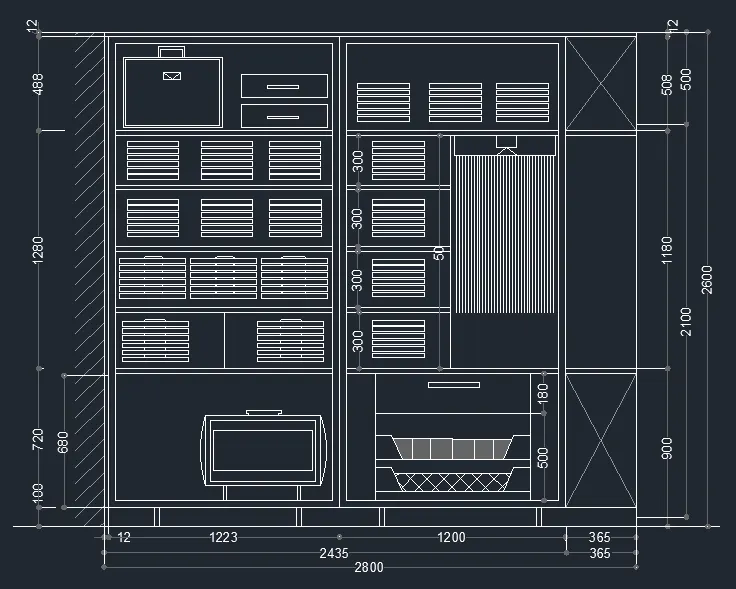
- Using the commands, Dim linear, Dim Continue the dimensions are marked for all the corners and spaces.

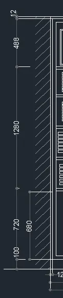
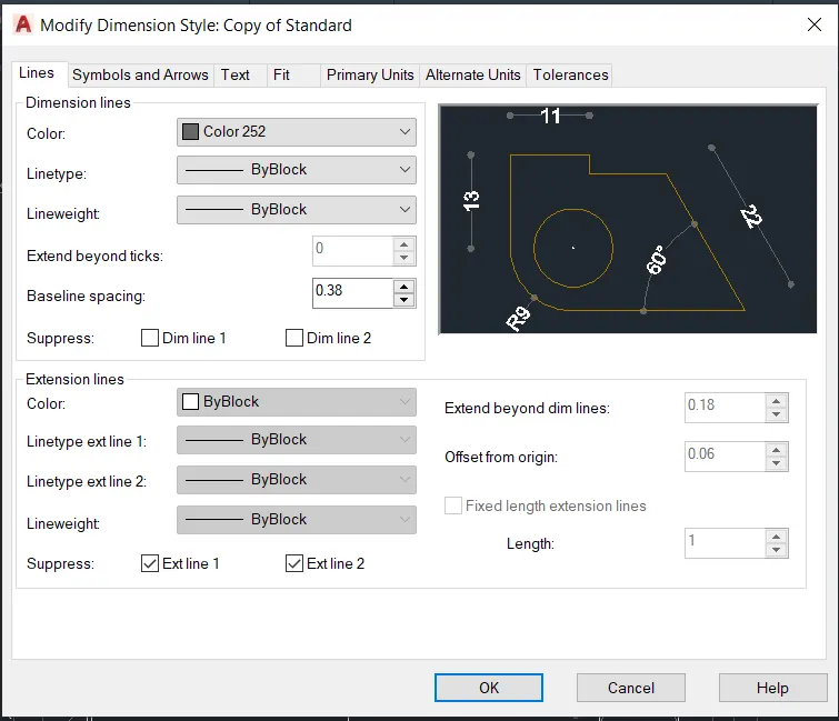
- Go to < Dimension style manager < select lines < suppress the extension lines < ok.
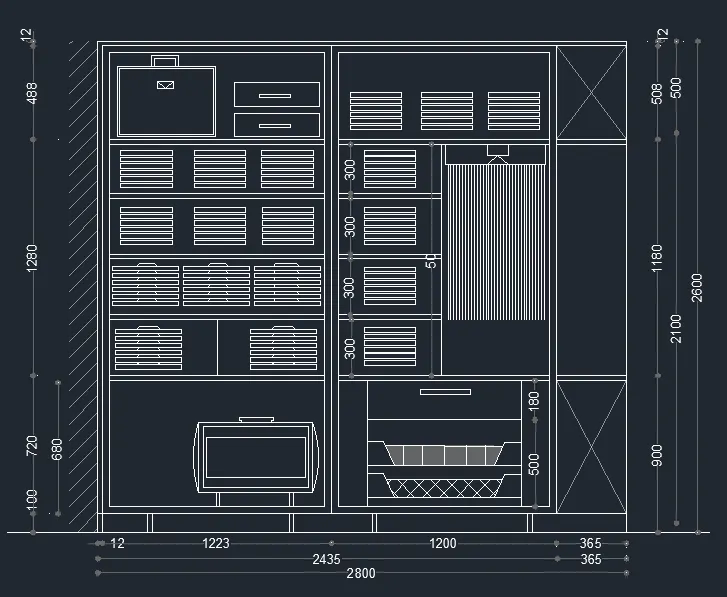
- The following pictures shows the dimensions after the suppression of extension lines.
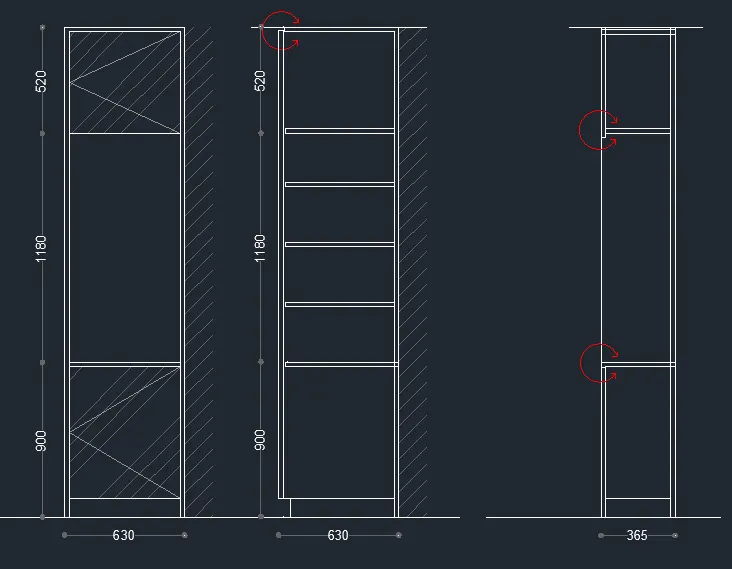
- Using the command, circle, line and trim, the detail arc is drawn and color is given as red.
- Using the command DText, the texts are mentioned at wherever required.
- And the following pictures, shows the diagrams with texts.
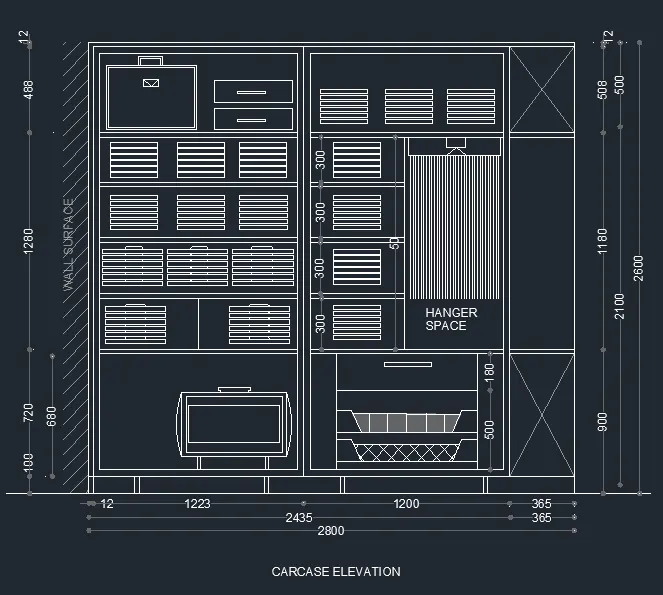
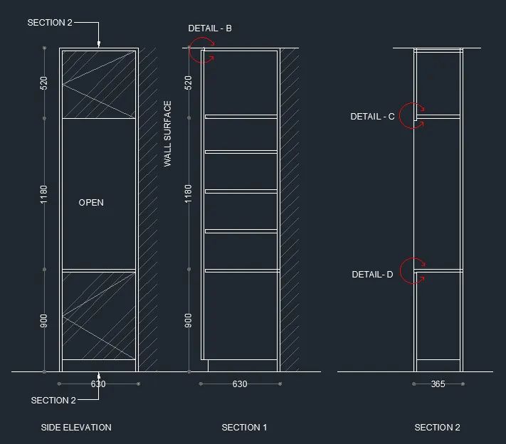
RESULT:
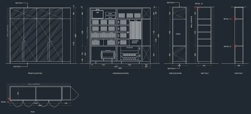
2.
AIM:
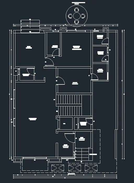
To draw the floor plan as shown in figure and explain the procedure step by step to obtain the result.
INTRODUCTION:
AutoCAD is a computer aided design software and drafting software application.
In this project, i have used various commands like,
* Line, XLine (horizontal and vertical), Polyline, Circle - to create the plan, windows, doors, stairs, canopy.
* Dtext - to mention the texts.
* Commands DIM Linear, DIM Continue - to create the Dimension lines.
* LAYERS - created individual layers for Plan, Dimensions, and texts.
* Fillet, Trim/erase, Offset, trim, ED - are regularly used at various places to complete the diagrams.
In the next step, the procedure is explained perfectly.
PROCEDURE:
- Open AutoCAD software
- Start from scratch
- Set the units to decimal and select ok
- Set limits as lower left corner (0,0) and upper right corner (1000,1000)
- Import the drawing pdf to AutoCAD to check the dimensions and start the drawing as per the given data.
- Go to layer properties < create new layers < name the layers for reference < close
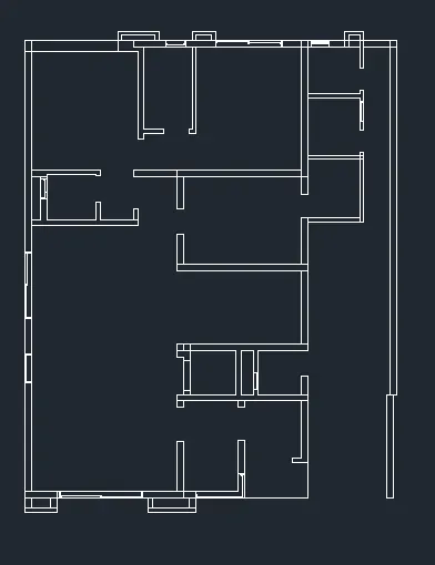
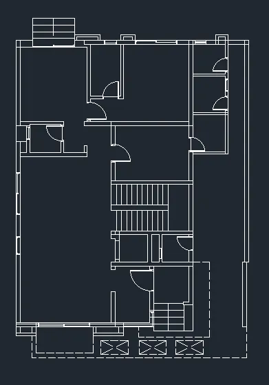
- With the help of reference diagram, the room dimensions are calculated and using the commands XLine(vertical and horizontal), line and trim options, the walls are created.
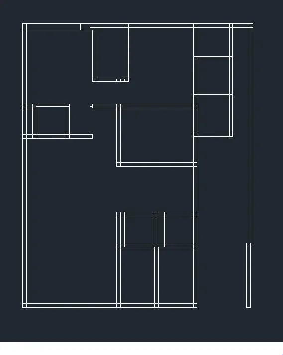
- Using the commands line and trim, the vents are created.
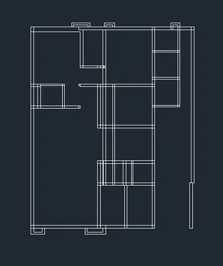
- Using the trim command, proper door space and the extra lines are deleted to create a floor plan.
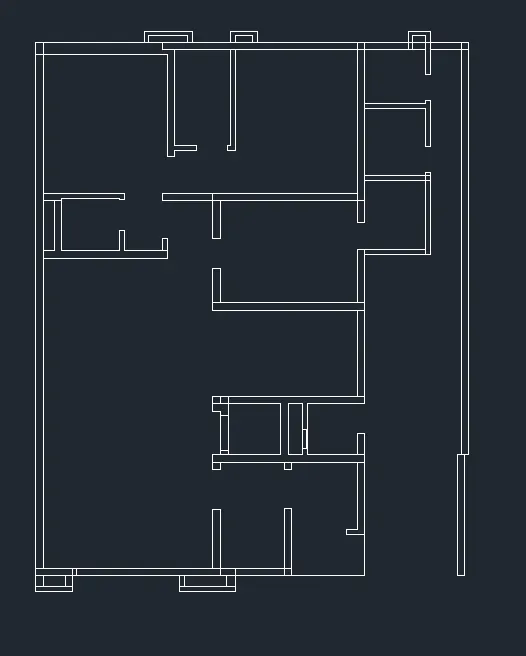
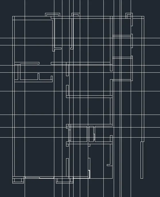
- Using the command XLine (vertical and horizontal), the windows and ventilation spaces in the walls are created.
- Using the line command, windows and ventilation panels are created separately.
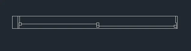
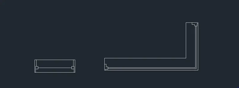
- Now, using the copy command, the windows and ventilation panels are placed in their spaces in the walls.
- Using the commands line, polyline and arc, doors are created separately.
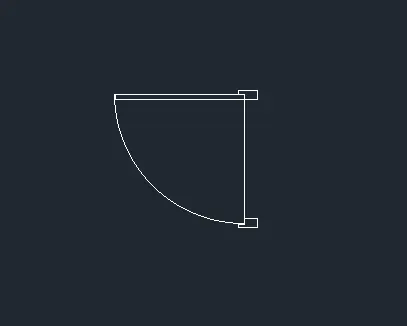
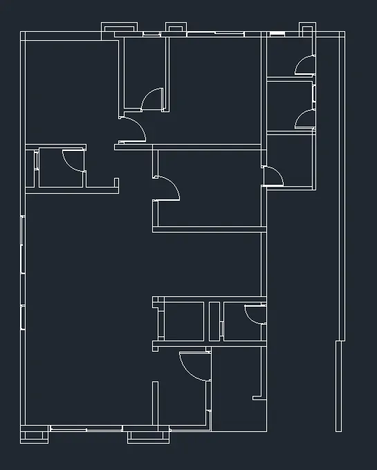
- Now, using the copy command, the doors are placed in their spaces.
- Using the commands line, and offset, the front end and back end steps are proveded.

- Go to
< Linetype manager
< Select Load option
< Choose ACAD_ISO02W100
< Apply
< ok.

- Select the line - ACAD_ISO02W100 and draw the front lawn section as shown in the diagram.
- Also, using the Line and offset commands, the staircase is drawn.
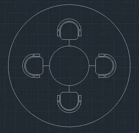
- As Canopy procedure has already been discussed in week 4 challenge, i have given a quick procedure here.
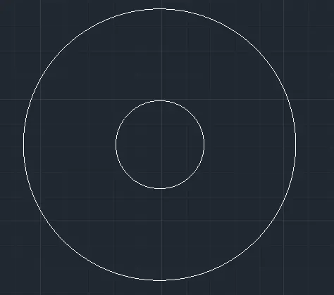
- With the same center point, draw 2 circles
- From the endpoint of the reference line, draw a line of 200 towards right and a line of 200 towards left, totally it makes a length of 400 horizontally.
- And from both the ends of horizontal line, draw a line of 200 vertically.
- Now, using fillet command join the two vertical lines.
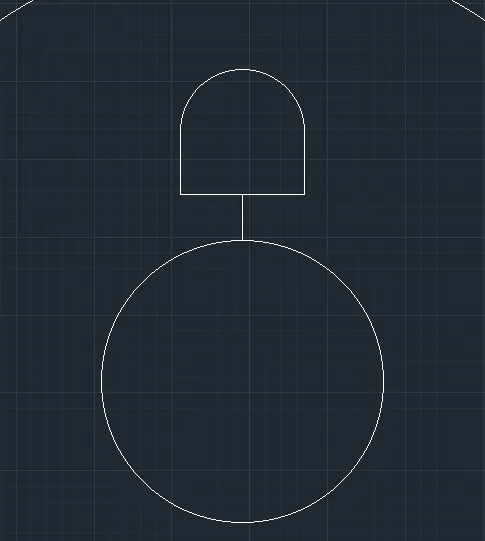
- Using fillet command, input (Radius 75) fillet the two bottom corners.
- Using offset command, offset the vertical lines and top bigger fillet to a distance of 20 towards outside.
- Again, using offset command, offset the previous one (the vertical lines and top bigger fillet) to a distance of 50 towards outside.
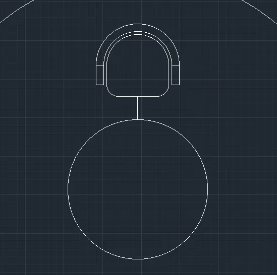
- Copy the seating area to other quadrants.
- Erase the reference lines.
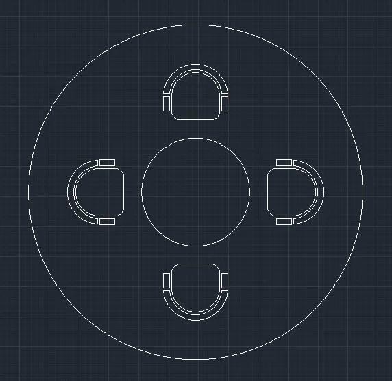
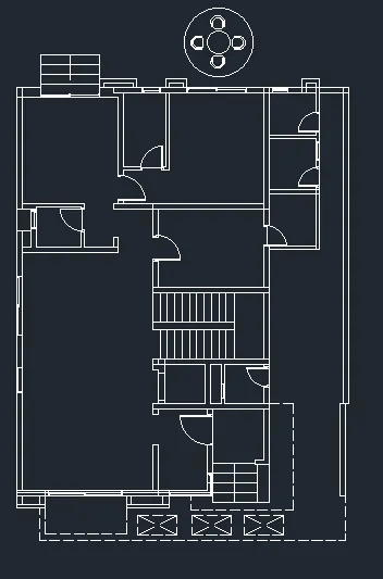
- Move the canopy to the Exact location as mentioned in the given diagram.
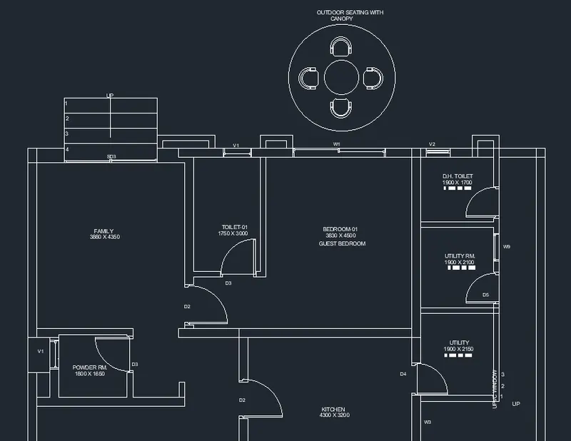
- Using Dtext command, the texts are created for each room, doors, windows and ventilations.
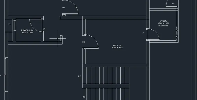
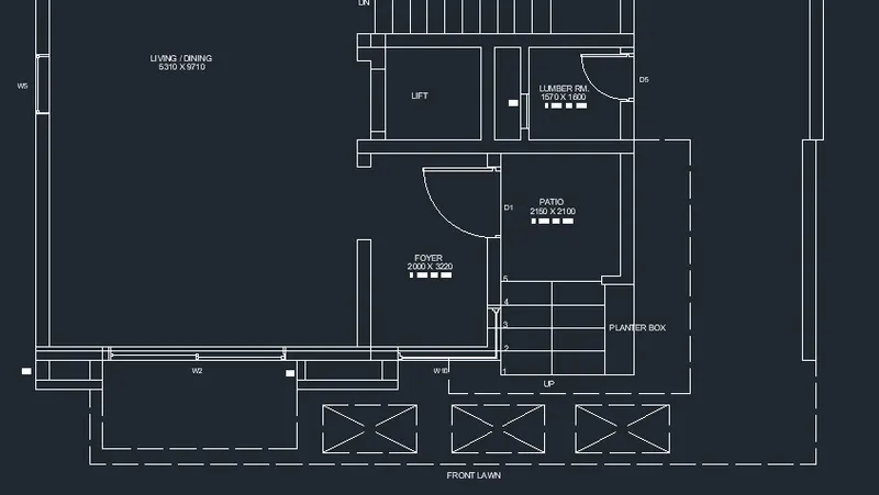
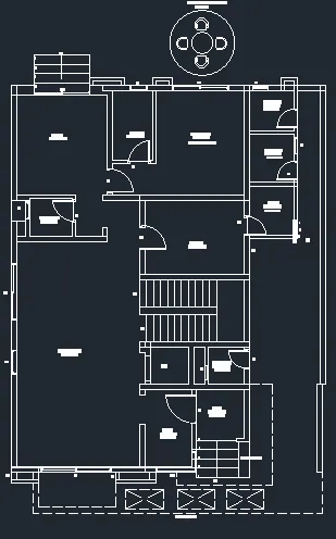
- Go to
< Dimension style manager
< In lines - Suppress the extension lines
< In symbols and arrows - Choose Dot, Arrow size - 1 and Break size 2
< In text - make Text height as 1
< Apply and ok.
- Using the commands, DIM Linear and DIM Continue, the dimensions are provided for all the spaces and corners.
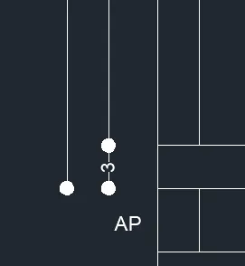
- The following picture shows the dimension break provided in the intersection.

- Diagram with dimensions provided.
RESULT:
3.
AIM:
To draw the kitchen layout as shown in figure using AutoCAD software and explain the procedure step by step to obtain the result.
INTRODUCTION:
AutoCAD is a computer aided design software and drafting software application.
In this project, i have used various commands like,
* Line, XLine (horizontal and vertical), Polyline, Circle - to create the plan, windows, doors.
* Dtext - to mention the texts.
* Commands DIM Linear, DIM Continue - to create the Dimension lines.
* LAYERS - created individual layers for Plan, Dimensions, and texts.
* Fillet, Trim/erase, Offset, ED - are regularly used at various places to complete the diagrams.
In the next step, the procedure is explained perfectly.
PROCEDURE:
- Open AutoCAD software
- Start from scratch
- Set the units to decimal and select ok
- Set limits as lower left corner (0,0) and upper right corner (1000,1000)
- Import the drawing pdf to AutoCAD to check the dimensions and start the drawing as per the given data.
- Go to layer properties < create new layers < name the layers for reference < close
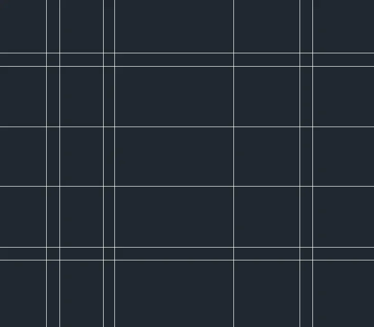
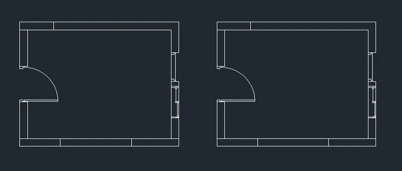
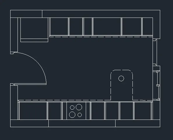
- Using the XLine command (Horizontal and vertical), draw the boundaries for the kitchen plan and mark the door and window spaces also.
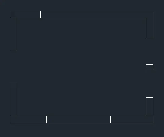
- Using Fillet and Trim Command, cut the lines as per the dimensions to form a kitchen plan.
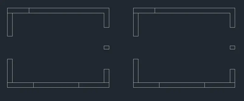
- Using Copy command, copy the same to draw above counter plan.
- Using the commands, line,polyline, and arc, the doors and windows are created separately.
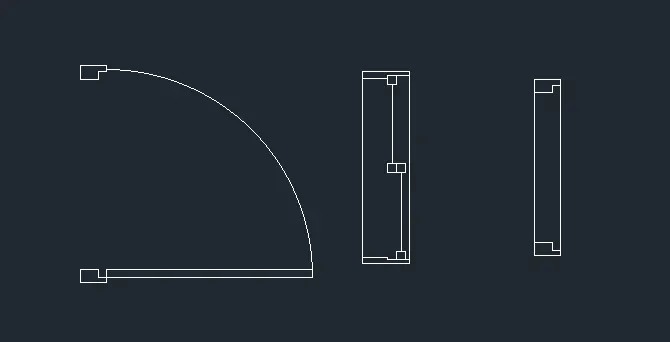
- Using the copy command, copy the doors and windows and place it in their spaces as per the diagram.
- Using the XLine, fillet and trim commands, the kitchen interior objects are created.
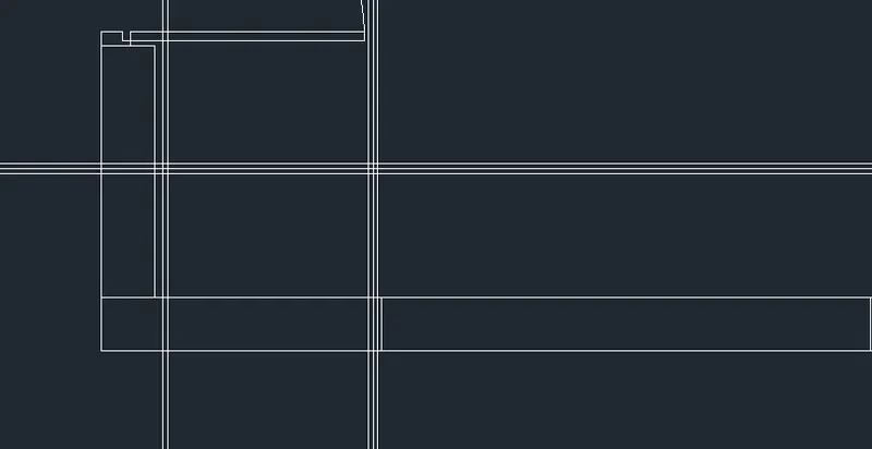
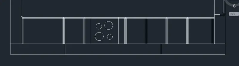
- The short dash line is chosen to draw the snack area.
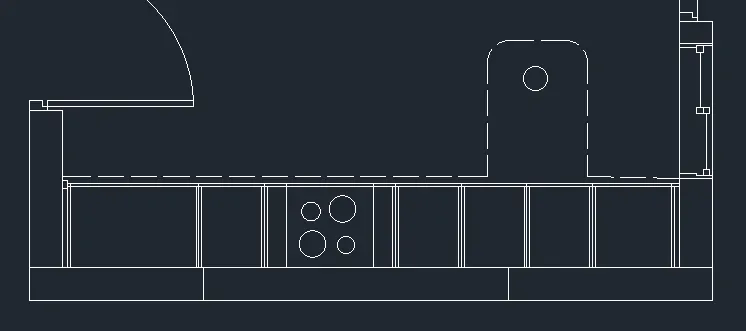
- Using the XLine, fillet and trim commands, the kitchen interior objects are created.
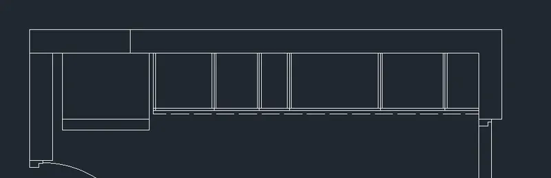
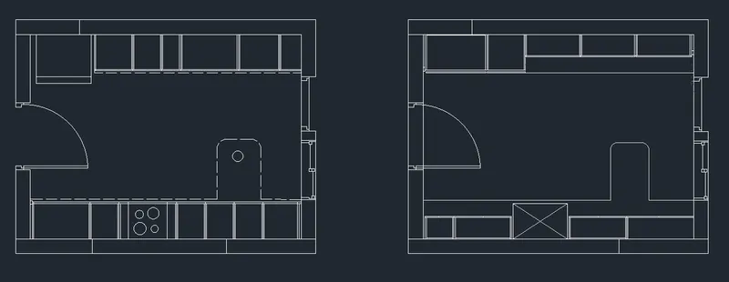
- Using the commands, DIM Linear and DIM Continue, the dimensions are marked for each objects created.
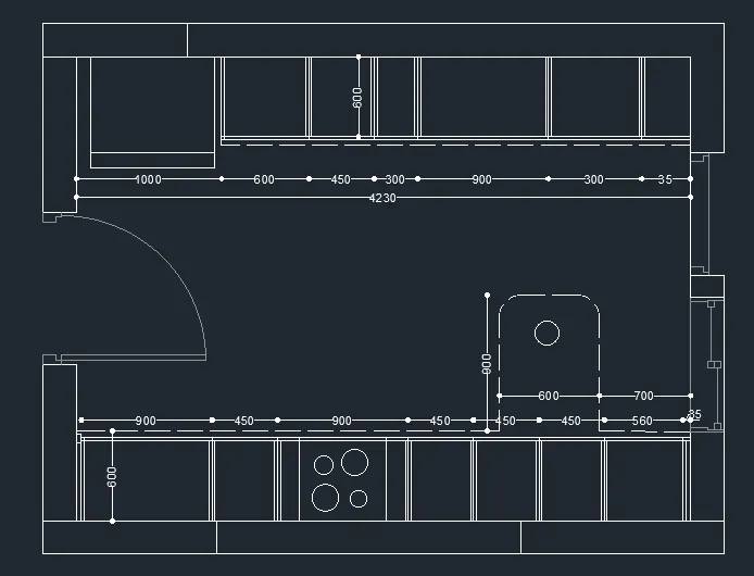
- Using the command DText, the texts are mentioned.
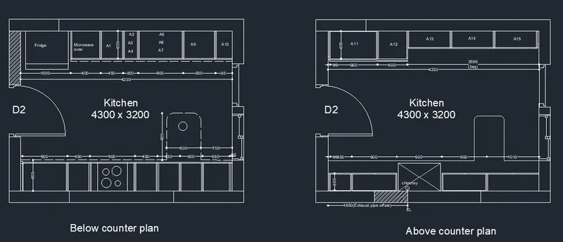
- Using the Hatch command, Hatch - ANSI32 and Solid fill is used to fill the wall.
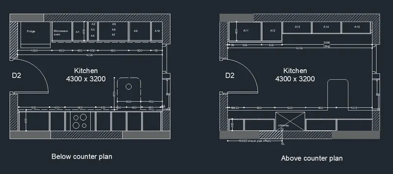
RESULT:
4.
AIM:
To draw the column details as shown in figure and explain the procedure step by step to obtain the result.
INTRODUCTION:
AutoCAD is a computer aided design software and drafting software application.
In this project, i have used various commands like,
* Line, circle - to draw the column and bars.
* Copy (Array) - to create multiple lines at equal spaces.
* Solid Hatch - to fill the bars.
* Dtext - to mention the texts.
* Fillet, Trim/erase, Offset, ED - are regularly used at various places to complete the diagrams.
In the next step, the procedure is explained perfectly.
PROCEDURE:
- Open AutoCAD software
- Start from scratch
- Set the units to engineering and select ok
- Set limits as lower left corner (0,0) and upper right corner (100',100')
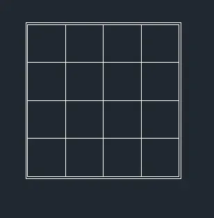
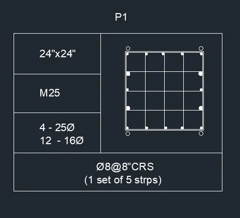
- Using the line command, draw two 40" lines at horizontal and vertical with one end connected.

- Using the copy (array) command, copy the lines at 10" equal spacing for both vertical and horizontal lines.
- Using offset command, offset the outer lines and fillet it.
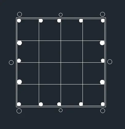
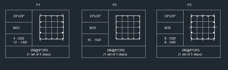
- Create 4-25mm dia bars (1" as per schedule) and 12-16mm dia bars (0.62" as per schedule).
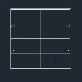
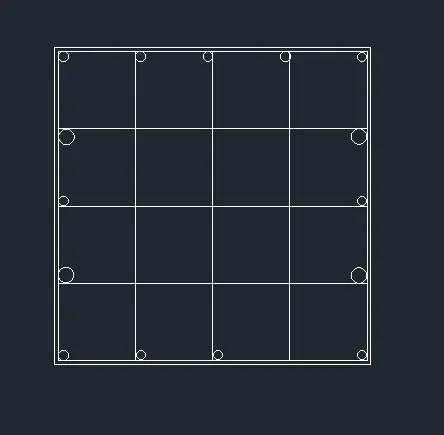
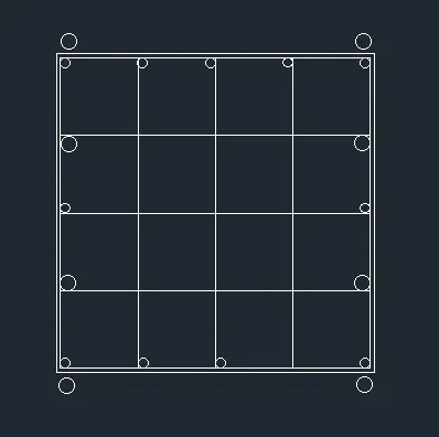
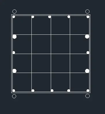
- Using Hatch command, Solid fill the bars.
- Using Dtext and line Command, mention the texts and create a table to fit the texts.
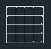
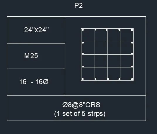
- Similarly for P2, Draw 16 - 16mm dia bars (0.61" as per schedule).
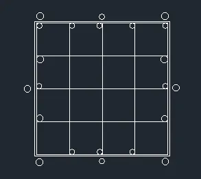
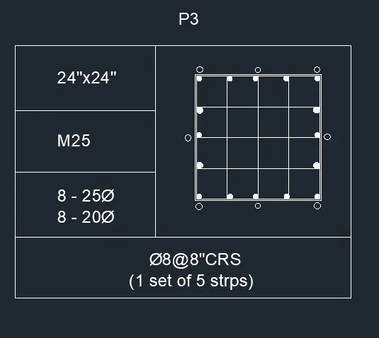
- Agian, for P3, draw 8-25mm and 8-20mm dia bars.
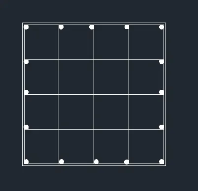
- Using Hatch command, Solid fill the bars.
- Using Dtext and line Command, mention the texts and create a table to fit the texts.
RESULT:
5.
AIM:
To draw the Raft Layout as shown in figure and explain the procedure step by step to obtain the result.
INTRODUCTION:
AutoCAD is a computer aided design software and drafting software application.
In this project, i have used various commands like,
* Line, XLine (horizontal and vertical) - to create the plan.
* Dtext - to mention the texts.
* Hatch - to fill the columns.
* Layers - created individual layers for layout, dimensions and texts.
* Commands DIM Linear, DIM Continue - to create the Dimension lines.
* Fillet, Trim/erase, Offset, trim, ED - are regularly used at various places to complete the diagrams.
In the next step, the procedure is explained perfectly.
PROCEDURE:
- Open AutoCAD software
- Start from scratch
- Set the units to enginnering and select ok
- Set limits as lower left corner (0,0) and upper right corner (1000,1000)
- Import the drawing pdf to AutoCAD to check the dimensions and start the drawing as per the given data.
- Go to layer properties < create new layers < name the layers for reference < close.
- Using the reference diagram, calculate the total dimensions and create the boundary lines and walls using the XLine, line and fillet commands.
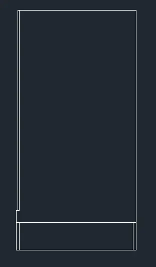
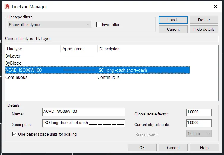
- Choose the line [Long dash short dash] to mark the grid lines.
- Using the long dash and short dash line, create the grid lines to mark the columns in the next step. Refer the given layout diagram for the distance between each grid lines.
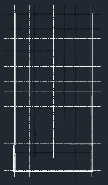
- The grid lines mention the center of each columns.
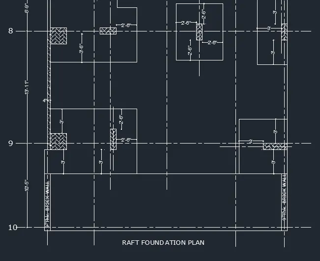
- Here, Columns of sizes 24" x 24" , 9" x 24", 9" x 18" are used.
- Using Hatch command, the Hatch AR-HBONE is used to fill the columns.
- Using Polyline command, the footing is drawn for all the columns, as per the dimensions given in the reference diagram.
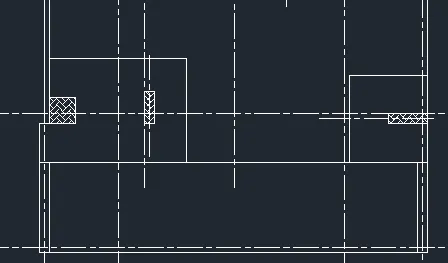
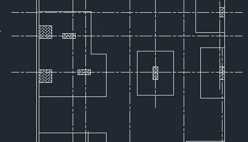
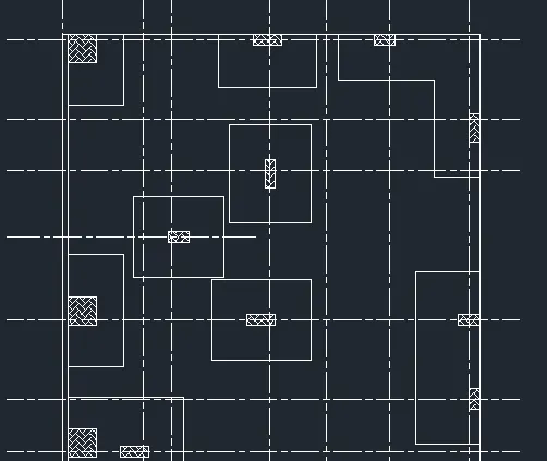
- The following picture shows the complete diagram after column marking and footing is done.
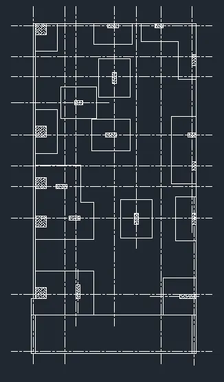
- Using the commands, DIM Linear and DIM Continue, the dimensions are marked for each grid lines.
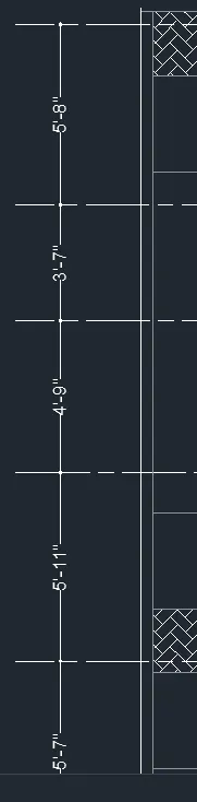
- Using the commands, DIM Linear and DIM Continue, the dimensions are marked for all the footings and columns.
- Using the command DText, the texts, names for each grid lines and title is mentioned.
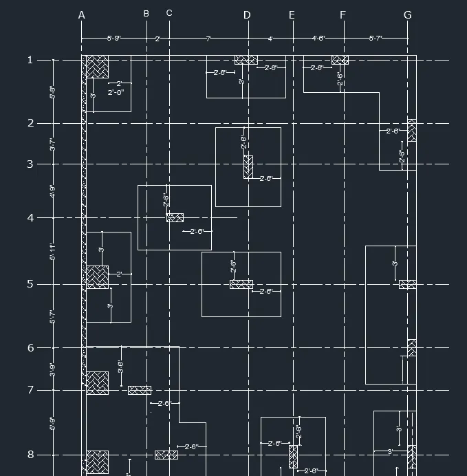
- The following picture shows the complete diagram after the dimensions and texts are given.
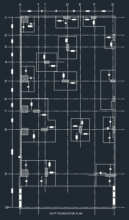
RESULT: