Creating a Wardrobe detailed drawing, Floor Plan, Kitchen Layout and Column Detail using AutoCad
AIM:
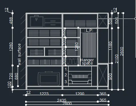
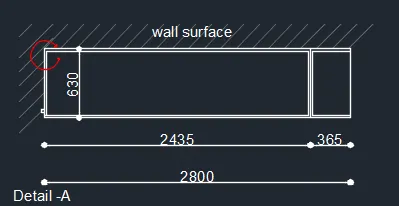
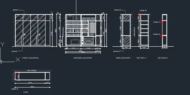
1. To Draw the elevation and details of a wardrobe as shown in the Figure below. After sketching, you need to provide the dimensions and text with the use of layers. Use proper text styles and dimension methods to document it. Also, assume dimensions, wherever needed.
Note: All dimensions are in mm.
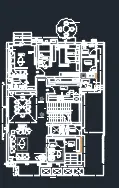
2. Draw the floor plan as shown in the Figure. Use the proper drafting tools to sketch the plan. Do not hatch or draw the furniture. You need to draw the floor plan with the following.
Note: You can also import the Floor_Plan.pdf into your current drawing and start working on the project. You need to scale the imported pdf file using reference option. All dimensions are in mm.
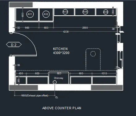
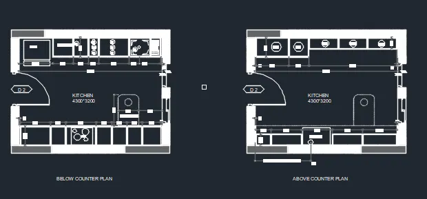
3. Create the Kitchen Layout as shown in the Figure below. Also, use proper dimension techniques to dimension the kitchen layout. Also, insert text wherever required. All dimensions are in mm.
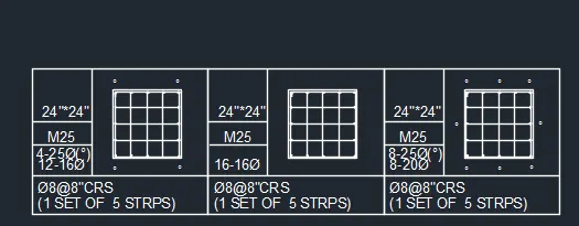
4. Sketch the column details as shown in Figure. Insert dimensions and text in the figure. Refer to the bar sizes from the schedule.
8mm ---- 0.31 Inches
25mm--- 1 inches
16mm—0.62 inches
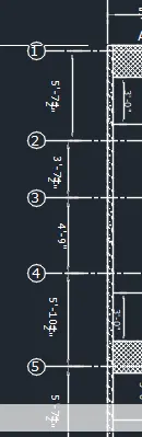
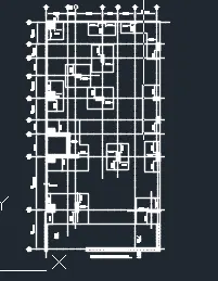
5. Draw the Raft Layout as shown in the Figure. Assume the column size as per your knowledge. You can take the sizes as: 24”x24”, 9” x 24”, 9” x 18”, and 9’ x 24”. You can import the raft_foundation.pdf to ensure the missing dimensions.
PROCEDURE:
1.Create two layers one 0 and the other one glass and set transperacy for glass layer to 70.draw the figure of the cabinet or its outer line in the 0 layer using line and offset command.
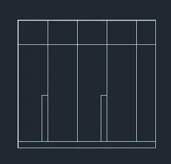
then go to glass layer and draw the lines with less transperacy. and add text and dimension using dtext with 90 rotation and dimlin continous command to give dimensions select the arrow head size and text size from properties according to the required dimension. select required dimension from dimstyle.
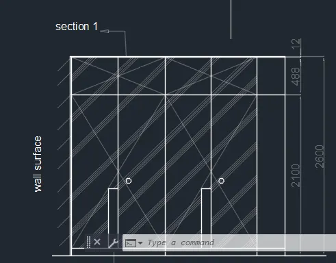
create a new layer items and set transperacy as 80 for it. then draw the outline using line, offset ,copy and trim command in the layer 0.
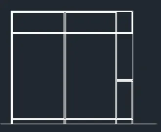
then draw the drawers using offset and teim command in o layer.
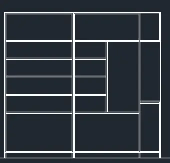
then go to glass layer and draw the linES and hatch the needed areas for drawers.
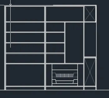
then make the current layer items and draw all the items using fillet, copy, scale and line tool .
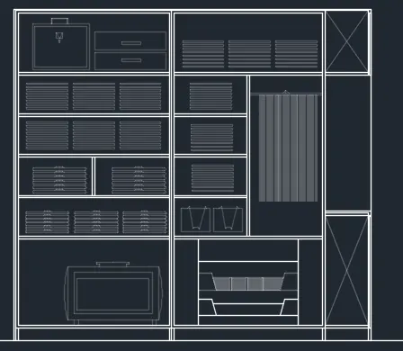
now enter all the text using dtext command and dimension it from annotate tab . using dimlin and dimcontinue command
then again using the line command and previous ways draw the remaining sections of cabinet and complete the drawing.
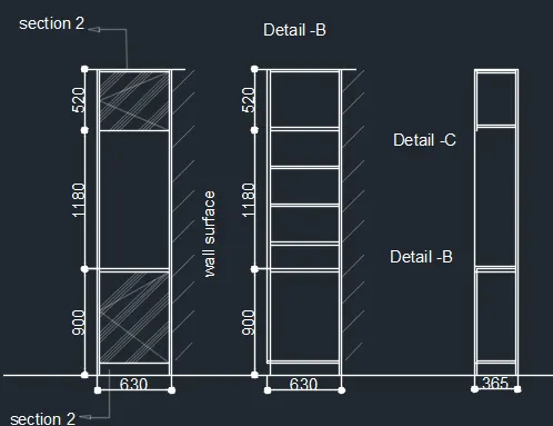
then using dtext command name the drawings.
2.
import the floor plan pdf from the insert tab import pdf option.
use dimstyle command and select standard . then check the dimension of the exterior wall which is 3.0884 .
then scale the object using scale command
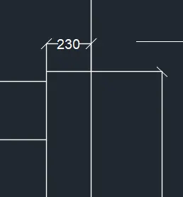
select the plan then choose a base point anywhere press enter then select the reference option and put the distance of the outer wall of the plan press enter and then put the referenced ditance as 230mm.
then go to dim style in select the arrowtype as oblique arrow size 50 text size 50 and precision as 0.
then using dimlin command dimcontinue and dimbaseline command dimension the whole drawing
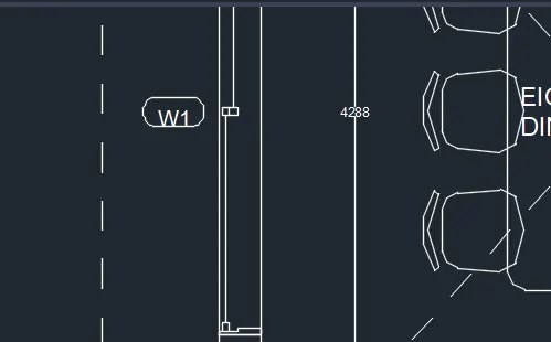
continue and dimension the whole drawing using dimcontinue command
3.
create the upper section of first figure using line offset and trim command .
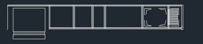
then draw the below part fromm the offset of 3000 to the above line . and then draw the exterior walls with offset of 230 mm and then join them. and draw the door .

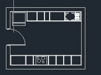
then draw the windows

then hatch the walls with hatch command and select ANS132 for the selected walls and other walls solid hatch
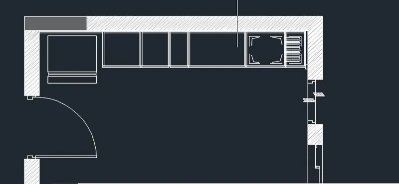
create dotted lines with transperacy 70 and select line type ACADISO 02W100
now dimension line and set dimension style required according to drawing from dimstyle command and use dimlin and continue command to dimension drawing
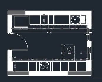
Now add text using dtext or mtext command.
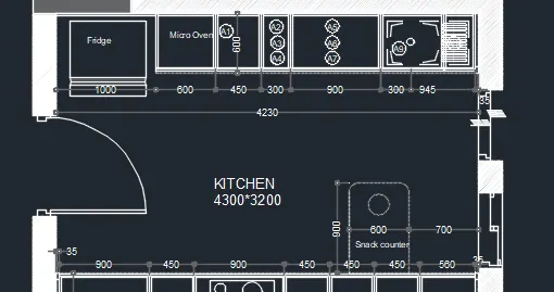
for figure 2 use the samemethods of drawing and adding text and to add text with dimension line use text edit command.
4.
create a table and add the required text using line and dtext command.
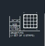
complete table and then copy and edit text.
5.
select unit architectural.
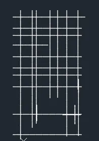
create a layer for grids and select the required line type and draw lines according to the drawing .
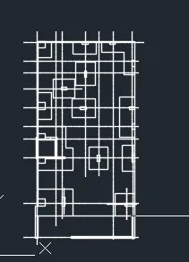
then import drawing for missing dimensions and draw the footing and column and wall as per the drawing,
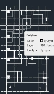
then hatch all the required parts differently such as for PCC different for walls different etc.
then create a layer text and another layer dimension.
in text layer using dtext command add all the texts.
in dimension layer go to dimension stle select the arrowheads and text size etc according to the drawing and then dimension all the line. select unit as architectural.
RESULT:
1.
2.
3.
4.
5.