Creating a Wardrobe detailed drawing, Floor Plan, Kitchen Layout and Column Detail using AutoCad
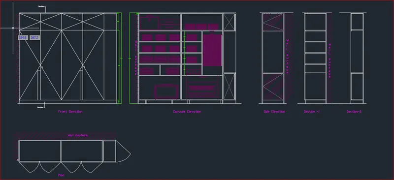
Q1) Draw the elevation and details of a wardrobe as shown in the Figure below. After sketching, you need to provide the dimensions and text with the use of layers. Use proper text styles and dimension methods to document it. Also, assume dimensions, wherever needed.
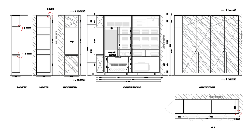
Aim: To draw the wardrobe elevations and details using all the necessary commands
Introduction: It is a piece of furniture for holding clothes, now usually a tall, upright case fitted with hooks, shelves, etc.
Page Setup:
Open UNITS
Select Decimal
Precision 0.00
Insertion scale millimeters
Apply okay
Commands Used:
Units, Limits, Line, Offset, Hatch, Dim linear, Dim style and trim.
Procedure
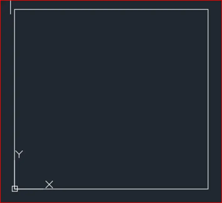
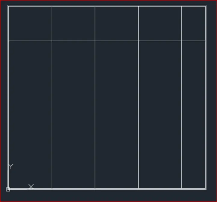
Draw the rectangle of 2800 x 2600mm
Draw the border of offset 12mm from corners
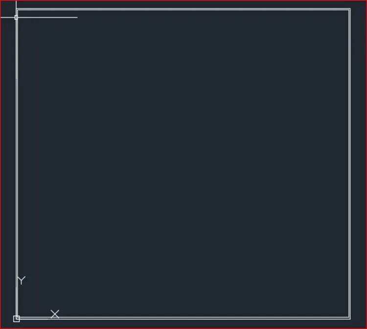
Using Explode tool break the rectangle
From the top make an offset of 488 mm from the top and 610 mm from left to right 4 lines
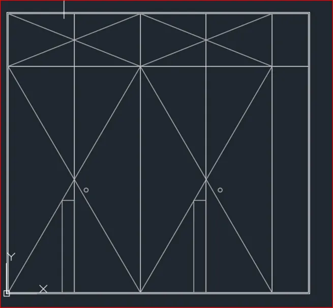
Draw the required lines to represent the wardrobes
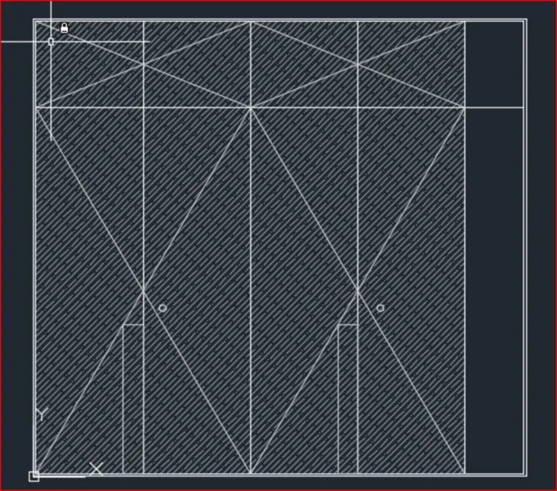
Using hatch command draw the outer surfaces
Using Dim linear and Dim text label neatly
Q2. Draw the floor plan as shown in the Figure. Use the proper drafting tools to sketch the plan. Do not hatch or draw the furniture. You need to draw the floor plan with the following:
Note: You can also import the Floor_Plan.pdf into your current drawing and start working on the project. You need to scale the imported pdf file using reference option. All dimensions are in mm.
- Walls (Exterior and Interior)
Wall Thickness: Exterior Wall- 230mm, Interior Wall: 150 mm (Wherever Required)
- Doors and Windows: Assume the size of the doors and window.
2.1Stairs: Tread-300mm, Riser-150mm
- Insert Text wherever required
- Insert the dimensions using proper techniques.
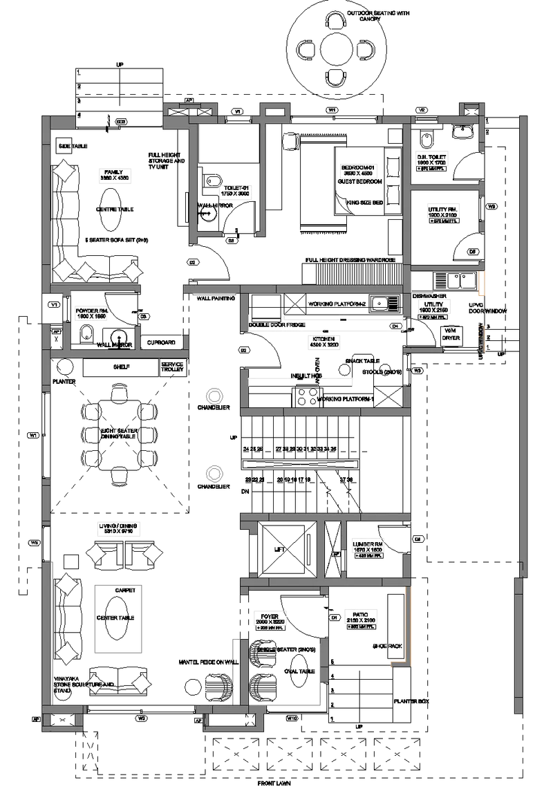
Aim:
To draw the given indoor plan with proper dimensions in the AutoCAD in detail
Introduction:
A floor plan is an architectural drawing showing the spatial layout of a building
It is a technical information such as dimensions, annotations, furniture’s, doors, windows etc.
Commands Used:
Limits, Line, Offset, hatch, dim linear command, units, extend, Fillet, Trim, Join, Line Weight, Line Type
Page Setup:
Open UNITS
Select Decimal
Units Feet
Apply okay
Procedure:
Draw the outer surface area
Hatch the walls
Draw the steps
Draw the lift area
Draw the Furnitures
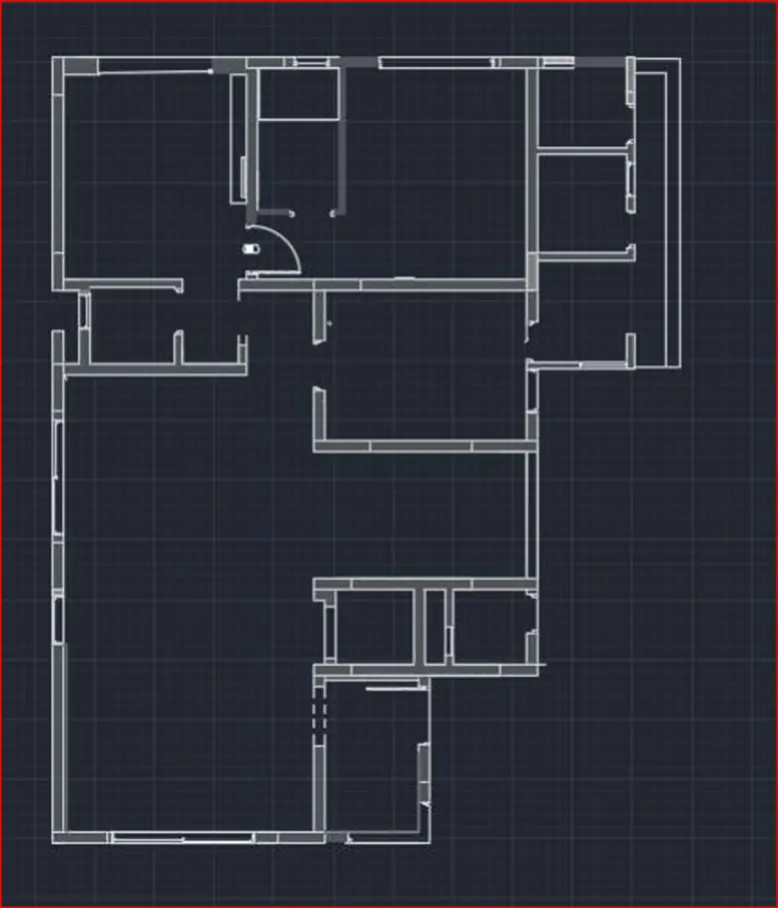
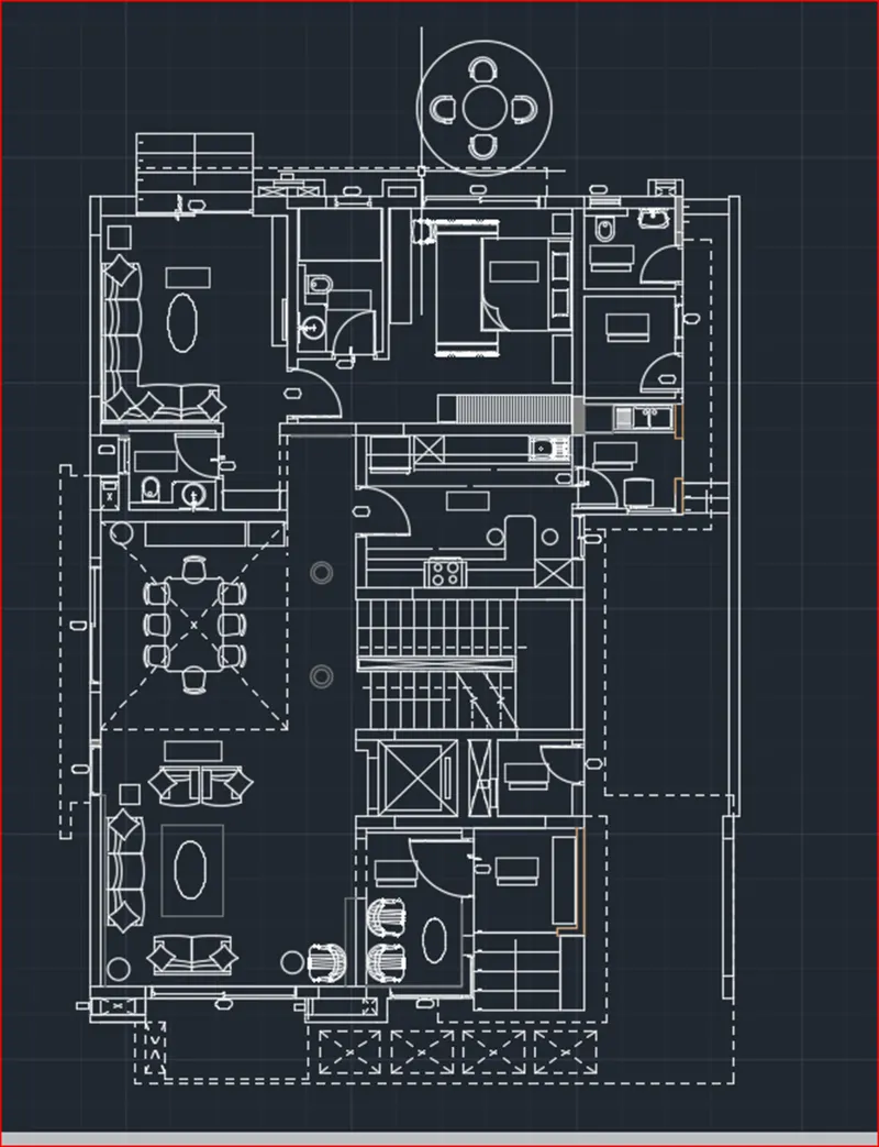
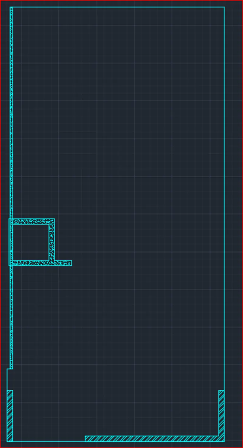
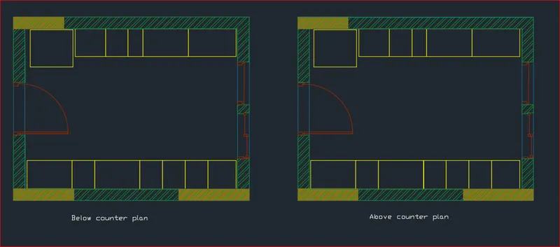
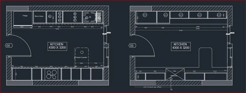
Q3. Create the Kitchen Layout as shown in the Figure below. Also, use proper dimension techniques to dimension the kitchen layout. Also, insert text wherever required. All dimensions are in mm.
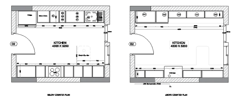
Aim:
To draw the kitchen layout with proper dimensions in the AutoCAD in detail
Introduction:
Kitchen layout is the most important part of designing your perfect kitchen.
It’s the layout that will determine how you can cook, how you eat and how you socialize.
Commands Used:
Limits, Line, Offset, hatch, dim linear command, units, extend, Fillet, Trim, Join, Line Weight, Line Type
Page Setup:
Open UNITS
Select Decimal
Units Feet
Apply okay
Procedure:
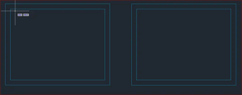
First draw the boundary of the plan using line command
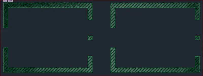
Draw the wall sections
Draw the columns
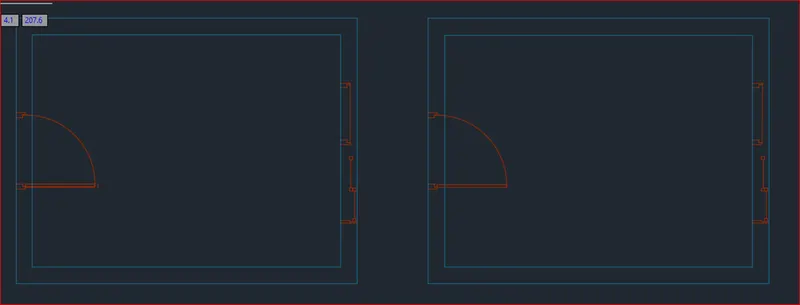
Draw the doors and windows
Draw the furniture
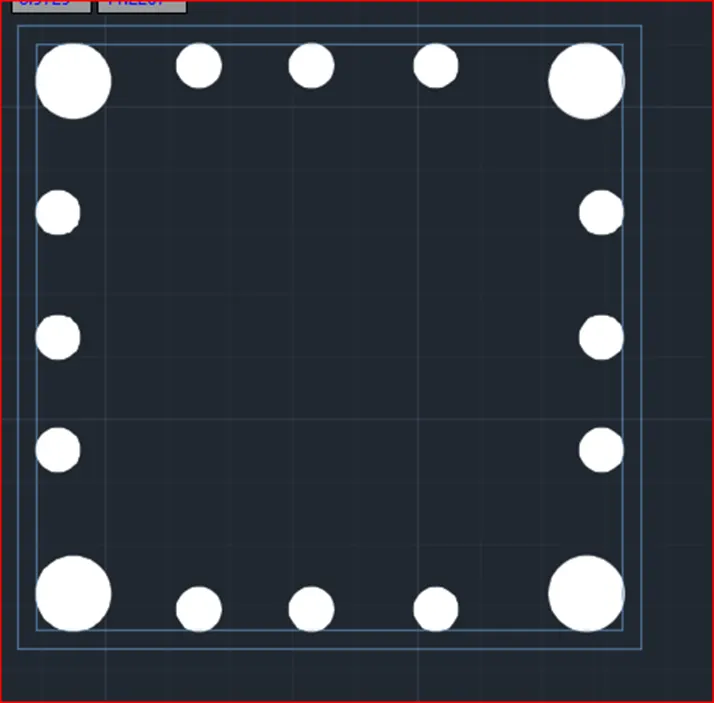
Q4. Sketch the column details as shown in Figure. Insert dimensions and text in the figure. Refer to the bar sizes from the schedule.
8mm ---- 0.31 Inches
25mm--- 1 inches
16mm—0.62 inches

Aim:
To draw the column details with proper dimensions in the AutoCAD in detail
Introduction:
Columns are the vertical members of a building structure that use to support the slabs and beams
It serves as a backbone of the structures so we can achieve hat we wanted in a given project
Page Setup:
Open UNITS
Select Architectural
Units Feet
Apply okay
Commands Used:
O snap, Limits, X Line, offset, hatch, dim linear, Dim style, Units, Extend, Fillet, Trim, Join, Line Weight, Line type, text, divide, extend, mirror
Procedure
Draw the rectangular column
Using circle make the circles
Using line command mark the reinforcement
Using text command mention the given data
Repeat this process for P1, P2 and P3
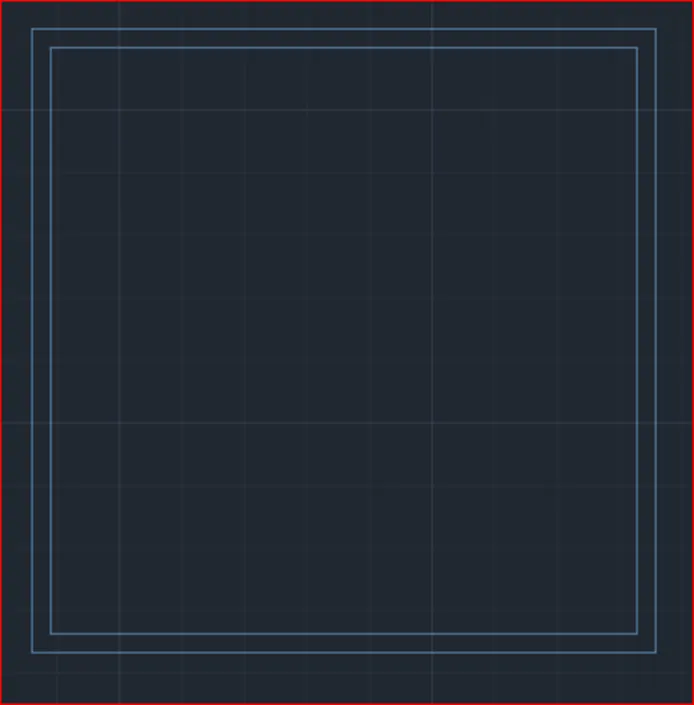
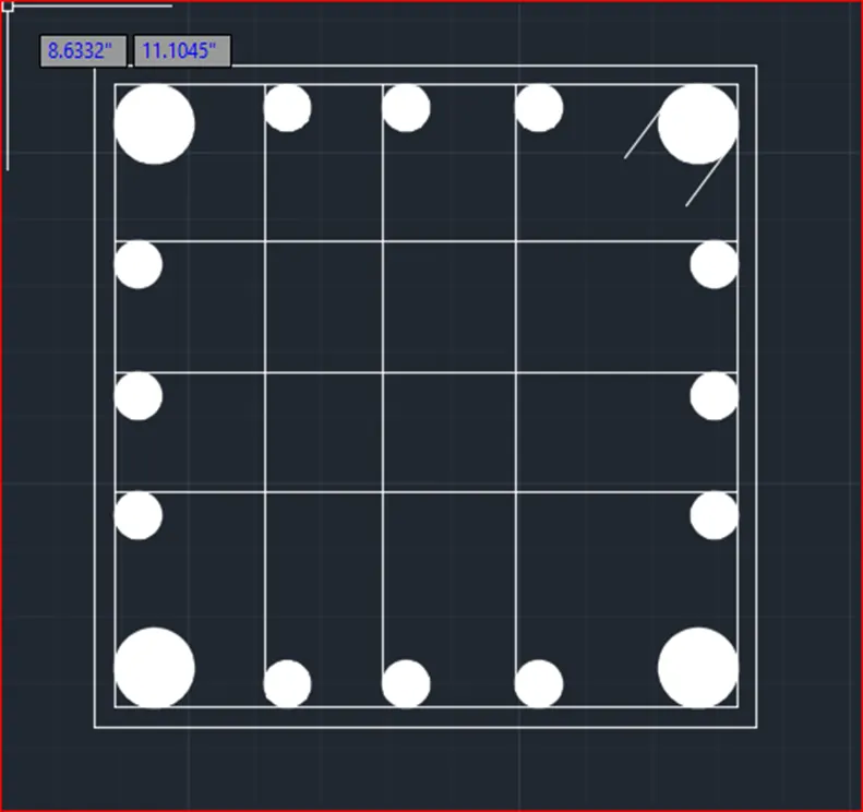
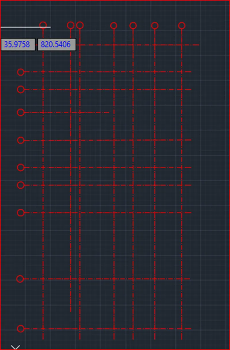
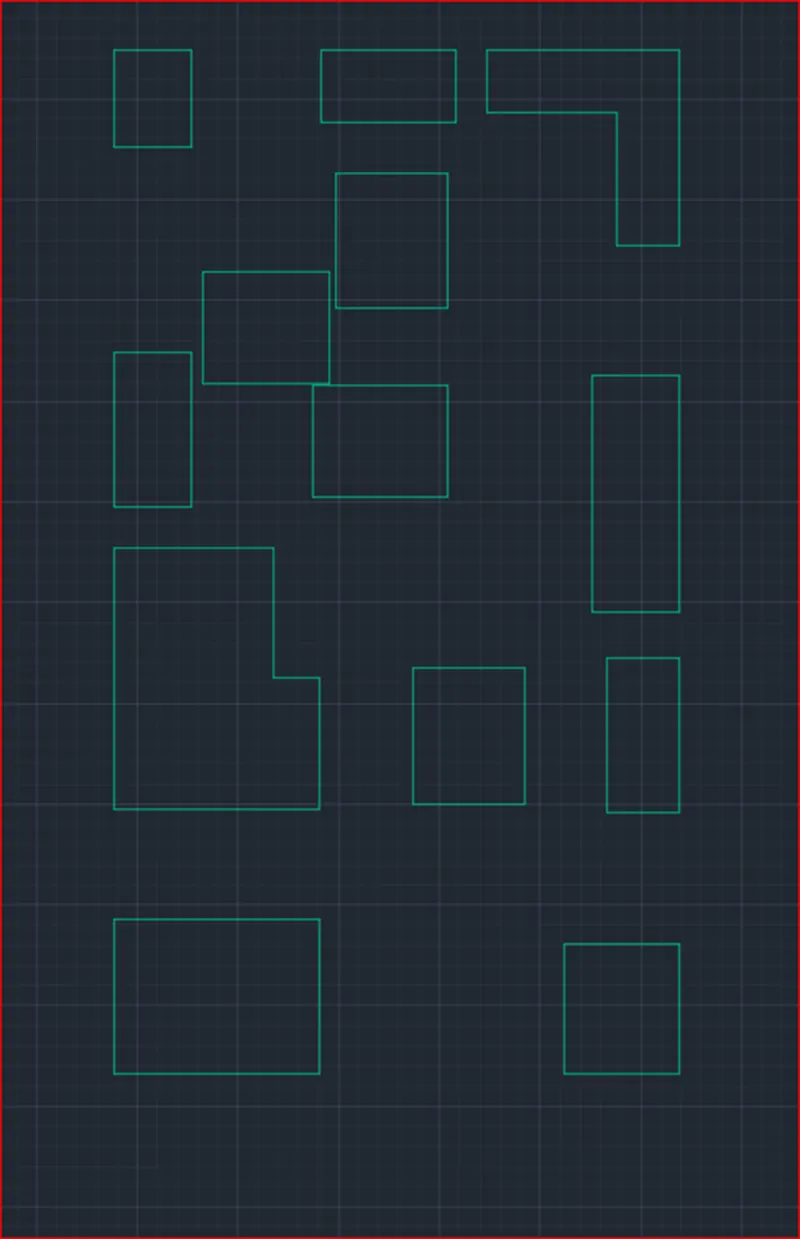
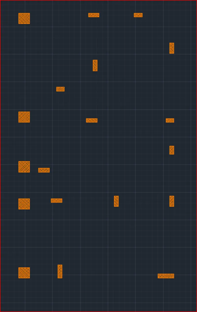
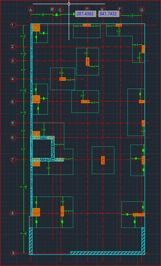
Q 5. Draw the Raft Layout as shown in the Figure. Assume the column size as per your knowledge. You can take the sizes as: 24”x24”, 9” x 24”, 9” x 18”, and 9’ x 24”. You can import the raft_foundation.pdf to ensure the missing dimensions.

Aim: To draw the raft foundation layout in the AutoCAD AutoCAD with proper dimensions in detail.
Introduction:
A raft foundation is a thick concrete slab resting on a large area of soil reinforced with steel, supporting columns, or walls and transfer loads from the structure to the soil.
Page Setup:
Open UNITS
Select Architectural
Units Feet
Apply okay
Commands Used:
O snap, Limits, X Line, offset, hatch, dim linear, Dim style, Units, Extend, Fillet, Trim, Join, Line Weight, Line type
Procedure:
Step 1:
Select the X line Command and draw the horizontal and vertical lines for drawing the raft layout.
Offset the horizontal and vertical lines as required and name them with alphabets and numbers.
Step 2:
Draw the columns and footings as per the required dimensions.