Creating a Residence Layout, Seating plan, Toilet and Utility room plan using AutoCad
Q1.
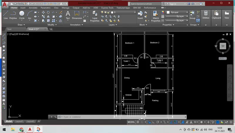
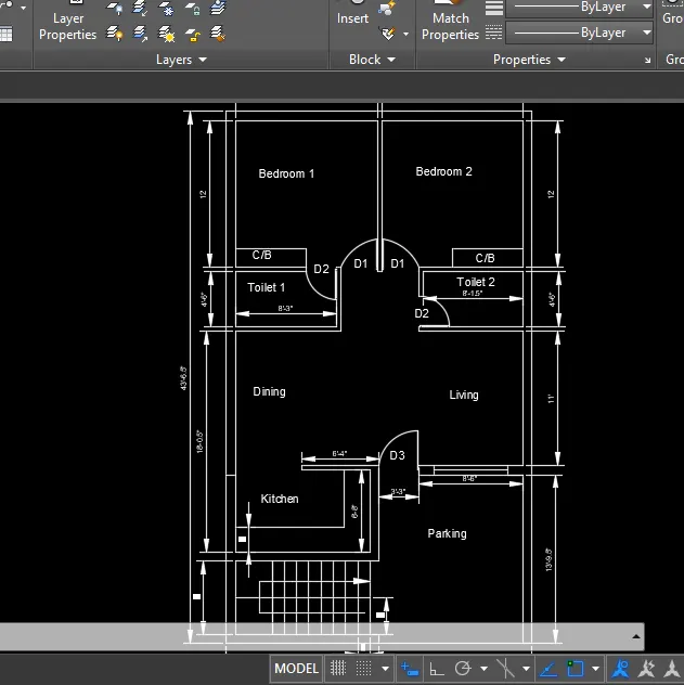
Aim: Sketch the layout of a residence as shown in the Figure 1.
Introduction:
- In Layout we can add, delete & rename the layers, change their properties, set property overrides in layout viewports & add layer descroptions.
- By giving Layer command.
- Layer list:
- New Layer: Creates a layer with a default name that you can immediately change.
- Name: Display the name of the layer or filter.
- Lay On & Off: It turns the selected layers On & Off. When the layer is On its visible & available for plotting & when its Off its invisible and not plotted.
- Freeze: It freezes the selected layers. Objects on frozen layer are not displayed, plotted or regenerated.
- Lock: Lock & Unlock the selected layers. Objects on the layers cannot be modified.
- Color: Display the selected colour dailogue box, where you can specify a color for the selected layer.
- Transparency: Display the Transparency dailog box, where you can specify a transparency for the selected layers.
- Plot style: Display the select plot style daiog box where you can change the plot style for the selected layers.
- Plot: Controls whether the selected layers are plotted. If you turn off plotting for a layer, the objects on that layer are still displayed. Layers that are off or frozen that are not plotted.
Procedure:
- In the command line type units Engineering & inches.
- Here Inner wall dimensions 9" & Outer wall dimensions 4.5"
- In the command line type Limax 100', 100'
- In the command line type z enter a enter.
- In the command line type XL (xline) & draw horizontal & vertical.
- For staircase in the command line type Offset of 1' for thread.
- In the command line type Offset of 9"
- In the command line type Offset of 3'
- In the command line type Offset of 3'
- In the command line type Offset of 9"
- In the command line type Offset of 2' & In the command line type trim and trim according to given plan
- For dinning room In the command line type Offset of 18.05'
- In the command line type Offset of 4.5"
- For Toilet 1 In the command line type Offset of 4'6"
- In the command line type Offset of 4.5"
- For Bedroom 1 write in the command line type Offset of 12'
- In the command line type Offset of 9" & as per the plan draw the further by using offset & trim
- For Bedroom 1 write in the command line type Offset of 12'
- In the command line type Offset of 4.5"
- For Toilet, In the command line type Offset of 4'6"
- In the command line type Offset of 4.5"
- For Living,In the command line type Offset of 11'
- In the command line type Offset of 9"
- In the command line type Offset of 13'9.5"
- Placing doors as per width & height given.
- For drawing window In the command line type Offset of 6'
Result:
Q2.
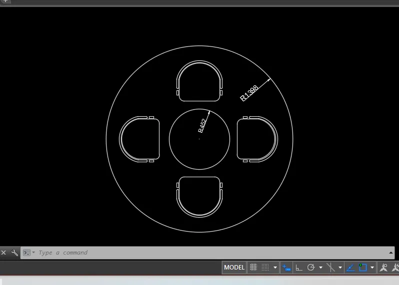
Aim: . Sketch the seating plan for an outdoor canopy.
Introduction:
- In Layout we can add, delete & rename the layers, change their properties, set property overrides in layout viewports & add layer descroptions.
- By giving Layer command.
- Layer list:
- New Layer: Creates a layer with a default name that you can immediately change.
- Name: Display the name of the layer or filter.
- Lay On & Off: It turns the selected layers On & Off. When the layer is On its visible & available for plotting & when its Off its invisible and not plotted.
- Freeze: It freezes the selected layers. Objects on frozen layer are not displayed, plotted or regenerated.
- Lock: Lock & Unlock the selected layers. Objects on the layers cannot be modified.
- Color: Display the selected colour dailogue box, where you can specify a color for the selected layer.
- Transparency: Display the Transparency dailog box, where you can specify a transparency for the selected layers.
- Plot style: Display the select plot style daiog box where you can change the plot style for the selected layers.
- Plot: Controls whether the selected layers are plotted. If you turn off plotting for a layer, the objects on that layer are still displayed. Layers that are off or frozen that are not plotted.
Procedure:
- In the command line type units , in mm & decimal.
- In the command line type Circle of radius 452
- In the command line type Circle of radius 1398
- In the command line type Rectangle , Fillet & Radius of 75mm
- In the command line type Trim and the trim it & In the command line type circle of 3 points & draw circle
- In the command line type Offset of 10
- In the command line type Offset of 30
- In the command line type Circle of 3 points on both side & trim it & then in command type rectangle of assumed dimensions.
- Ortho mode ON & In the command line type Copy
- In the command line type Rotate.
Result:
Q3.
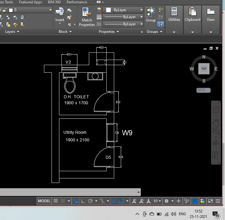
Aim: Sketch the part plan for the toilers and utilities room.
Introduction:
- In Layout we can add, delete & rename the layers, change their properties, set property overrides in layout viewports & add layer descroptions.
- By giving Layer command.
- Layer list:
- New Layer: Creates a layer with a default name that you can immediately change.
- Name: Display the name of the layer or filter.
- Lay On & Off: It turns the selected layers On & Off. When the layer is On its visible & available for plotting & when its Off its invisible and not plotted.
- Freeze: It freezes the selected layers. Objects on frozen layer are not displayed, plotted or regenerated.
- Lock: Lock & Unlock the selected layers. Objects on the layers cannot be modified.
- Color: Display the selected colour dailogue box, where you can specify a color for the selected layer.
- Transparency: Display the Transparency dailog box, where you can specify a transparency for the selected layers.
- Plot style: Display the select plot style daiog box where you can change the plot style for the selected layers.
- Plot: Controls whether the selected layers are plotted. If you turn off plotting for a layer, the objects on that layer are still displayed. Layers that are off or frozen that are not plotted.
Procedure:
- In the command line type units , in mm & decimal.
- Here Inner wall dimensions 150mm & Outer wall dimensions 300mm.
- In the command line type Xl & draw Horizontal & Vertical line
- In the command line type Offset of 300
- In the command line type Offset of 2100
- In the command line type Offset of 150
- In the command line type Offset of 1700
- In the command line type Offset od 300
- In D.H.Toilet place basin & Toilet by going in View ,Design center, select Tree View Toggle & select Toilet top view & Basin.
- In the command line type Offset of 631 i.e Placing ventillation.
- In the command line type Offset of 1900
- In the command line type Offset of 300
- In Utility Room for placing door D5 in the line command type Offset of 828
- For placing window W9 728
- In D.H.Toilet for placing door in line command type Offset of 832
- On top of right side of outer ext wall. In the command line type Offset of 201
- In the command line type Offset of 300 for outer wall
- In the command line type Offset of 402
- In the command line type Offset of 300
Result: