Creating a Residence Layout, Seating plan, Toilet and Utility room plan using AutoCad
1.
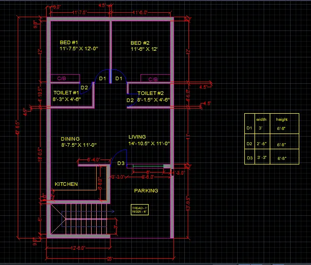
AIM: To sketch the layout of a residence considering all dimensions as reference to sketch given.
PROCEDURE:
step1: set the units to engineering and set the insertion scale to inches.
step2: Go to dim style and set the primary units to engineering units and keep 0'.00"
step3: Select the layer properties from the the layer panel of the Ribbon tab and create the layers
step4: Give the first day as dimension giving its colour red Next Layer of door as blue,Next Layer of hatch giving the colour 252, layer kitchen with colour 30,Layer of staircase with colour 11, Layer of texts of colour yellow, Layer of walls giving the colour 222,Layer of Windows with colour 112. Keeping the line weight as default and give the line type as continuous.
step5: Drawing the exterior walls from a given plan.While drawing the walls select on the wall layer from the layer panel of the Ribbon tabs and set it to current.
step6: Select the line tool and draw the line of breath 25 feet and height 43 feet 6.5 inches
step7: In the bottom left Corner from a distance of 12 feet 6 inches draw a line of width 6'
step8: Draw a line perpendicular to the line of length 6 feet from the midpoint
step9: Give the line weight of that particular line as 0.35 mm.Draw this line by keeping the staircase layer as current layer and override that line by giving the different colour
step10: Now offset the 6 feet height to a distance of 1 feet And draw 9 such lines
step11: Press escape and give the dimension simultaneously keeping the the first arrowhead oblique s arrowhead oblique and leader oblique in the symbol and arrows option of the modify dimension style and set that to current.
step12: Select a single line text by keeping the text layer at the current layer and write the text parking keeping the text height to be 9 inches
step13: Draw the window of 6 feet from a distance of 1 feet 3 inches from the outer wall
step14: Now keep the layer of the door as current and draw the door using the arc tool from a distance of 3 feet 3 inches from the internal wall
step15: Now for the kitchen keeping the kitchen layer to be the current layer draw a line of of length 9 feet from a distance of two feet
step16: press esc and draw vertical line touching the internal wall of height 6 feet 8 inch and offset that line to a distance of 2 feet in the left
step17: Select the trim tool and trim the the line that intersect in the middle
step18:Select the multi touch option and give the text as kitchen of text height of 9 inches
step19: Similarly use a Multi Text option keeping the text players to the current layer and give the text dining living toilet 1, toilet 2, bed #1, bed #2, D1, D2, D3 texts.Press esc and give all the necessary dimensions giving the angle of the text As 90°. press esc.
RESULT:
2.
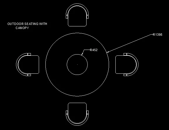
AIM: To sketch the seating plan for an outdoor canopy.
PROCEDURE:
step1: Set the units to decimal.
step2: Go to Dimstyle and set the primary units as decimal keeping the precession as 0.
step3: Select the centre radius tool from the ribbon.
step4: Now specify the cursor at any point and draw a circle of radius 1398 units.
step5: Keeping the geometric centre on in the snap mode.
step6: Draw another circle from the same centre of radius 452 units concentric to the bigger circle.
step7: press esc. Select the centre radius tool from the ribbon and draw a circle of radius of assumed dimension of 400 units.
step8: Now select the array tool from the modify ribbon, then press enter and select the polar array option and select the source object as the the 400 unit radius, and specify the centre point and draw the array.
step9: Edit and change the items to 4.
step10: Select the array and click on the edit source option.
step11: Now select the source item in the array.
step12: Draw a line tangent to the circle extending in a negative x axis twelfth of 500 units and enclosed it to the bottom arc of the circle tangentially,Keeping the ortho mode on.
step13: By editing the source object all the other arrays will get edited simultaneously
step14: Select the dream option entry in the inner half circumference of the circle
step15: Now escape and select the flillet option.
step16: Click on multiple option in the command box,Then click on radius option in the command box itself and assume the radius to be 80 units.
step17: Now select the vertex and fillet it and press escape.
step18: Select the offset tool from the modify panel of ribbon and offset the arc to a distance of assume dimension 20 units
step19: Again offset the outer Arc to a distance of assume dimension of 80 units.Press enter.
step20: Now select the line tool from the draw panel of ribbon and join the The endpoints of the two arcs.
step21: Press escape.
step22: Now select the rectangle tool from the draw panel of the ribbon.
step23: Draw a rectangle of assumed dimension aligned with the endpoints of the arcs and press escape.
step24: Select the dropdown for edit option and select the save changes option.
step25: Now give the necessary dimensions.
step26: Select the Multiline Text option from the drop down text tool from the modify panel of the Ribbon tab
step27: Give the text height as hundred write down the title and press esc.
RESULT:
3.
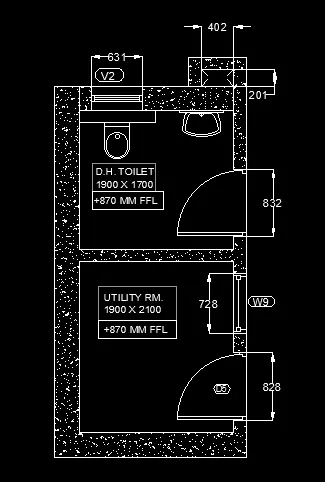
AIM: To sketch the part plan for the toilers and utilities room considering the outer wall thickness as 300mm and inner wall thickness as 150mm and assuming the missing dimensions.
PROCEDURE:
step1: Type units in the command box go to the units and set the units as decimals and set to miimeters.
step2: Go to dimstyle and in the primary units,in that set the unit format of linear dimension as decimal with the Precision of zero.
step3: For exterior walls:
Select the line tool and specify the cursor at any point.
Draw the interior dimension of the D.H. toilet as 1900 mm horizontal and 1700mm vertical
Press escape and select the offset tool and give the offset distance as 300 mm for outer/exterior walls.
Extend the outer wall vertically such that the total distance of the outer wall extended vertically is 4550mm.
The horizontal outer distance of the exterior wall is 2350mm.
step4: For D.H. TOILET room:Draw a horizontal line of distance assumed as 933.1 mm extending to the right from the top left corner continent to extend the line in vertical direction giving the height of 150 mm.
Press escape.
From the the midpoint of the centre line and draw a line 150 mm to both the the sides from the centre line to get a line of 300 mm.
Offset this 300 mm horizontal line to a distance of 40 mm in the downward direction
Draw another line from the end point of the 40 mm vertical line tour distance of 252.3 mm height
Press escape and select the circle of centre radius form and draw the circle to a distance of 129.8 mm of radius 25 mm from the endpoint of the line drawn.Delete the previously draw line.Select the centre radius circle tool and draw two circles of 130 mm radius intersecting each other and then use the trim tool to trim the inner circumference of both the circles
Select the move tool from the modify panel of the Ribbon tab and move the semi circle to a distance of 45.1 mm for away from each other.
Use the offset tool from the modified panel of the Ribbon tab and of said the lowest semicircle to a distance of 20 mm out words and join the geometry.
Now,for the WASH BASIN:From a distance of 300 mm from the toilet pot draw the wash basin and specify the point and draw a vertical line of 20 mm height and extend the line to draw the horizontal line of length 540 mm.
Offset the same horizontal length to a distance of 20 mm downward and join the geometry
now,from the centre point vertical height of 44.8mm draw a circle of radius 5 mm showing the sink of the washbasin. Draw the circle from the same centre of radius 15 mm concentric to the smaller circle.
Select the line tool and draw the height off 31.8 mm joining the smaller circle to horizontal length of 12.9 mm draw a circle of radius 7.5 mm.Press escape and then select the mirror tool from the modified panel of the Ribbon tab.
Select the circle and the the length to Mirror and specify the point of reflection to get the mirror image of the same in the left side.
Draw a line of 243.9mm 20 of the distance of 20 mm downward. Draw a arc of radius 30 mm on both the endpoints of the line. Draw an Arc 364.5mm and then of set the arc to a distance of 32.4 mm. Press esc.
WINDOW "V2":From a distance of 450 mm from the endpoint of the outer wall draw a vertical line of height equal to the height of the exterior wall that is 300 mm.
Select the offset tool from the modified panel of the Ribbon tab
Offset the vertical line to a distance of 631 mm.
Now draw a line joining the to vertical height enough said that horizontal 92 distance of 150 units that will give the central line.
now offset that Central Line to a distance of 10 mm on both the sides
Now delete the centre line. Offset the upper horizontal line to a distance of 30 mm upward and similarly do for the the lower horizontal line
Draw a vertical height of 80 mm distance of 40 mm from the extreme ends.
Press escape and select trim tool from the modified panel of the Ribbon tap and trim the lines in between the end vertical line and the previously drawn vertical line.
Select the Multi Text from the annotation panel of the Ribbon tab and drag the text line in between the window and give the text V2 for the ventilation window
Select the rectangle and enclose the text in a rectangle and draw the arcs at the end and now trim the the vertical height of the rectangle. Again select the Multi Text line option from the annotation panel of the Ribbon tab and give the text DH toilet 1900 x 1700
+870 MM FFL
Press esc.Draw the door of width 832 and use the the Arc tool to show the door.
Press escape and now select the dimensions tool from the annotation panel of the Ribbon tab to give the necessary dimensions.
step5:For UTILITY room:select the Multi Text option from the the annotation panel of the Ribbon tab drag the line in the middle of the second room and give the name is as "UTILITY RM. 1900 X 2100
+870 MM FFL".
from a distance of 150 mm from the inner wall of the utility room draw a window of height 728 mm.
Medicare: Select the single line text option and give the text as W9.
Press escape and now from a distance of 244 mm draw the door of of width 828 mm.
Use the arc to draw the door D5
Press escape and give the necessary dimensions
Select the hatch tool from the draw panel of Ribbon tab and give the AR-CONC has to the interior and exterior walls.
Press escape.
RESULT: