Creating a Residence Layout, Seating plan, Toilet and Utility room plan using AutoCad
1. Residence Plan:
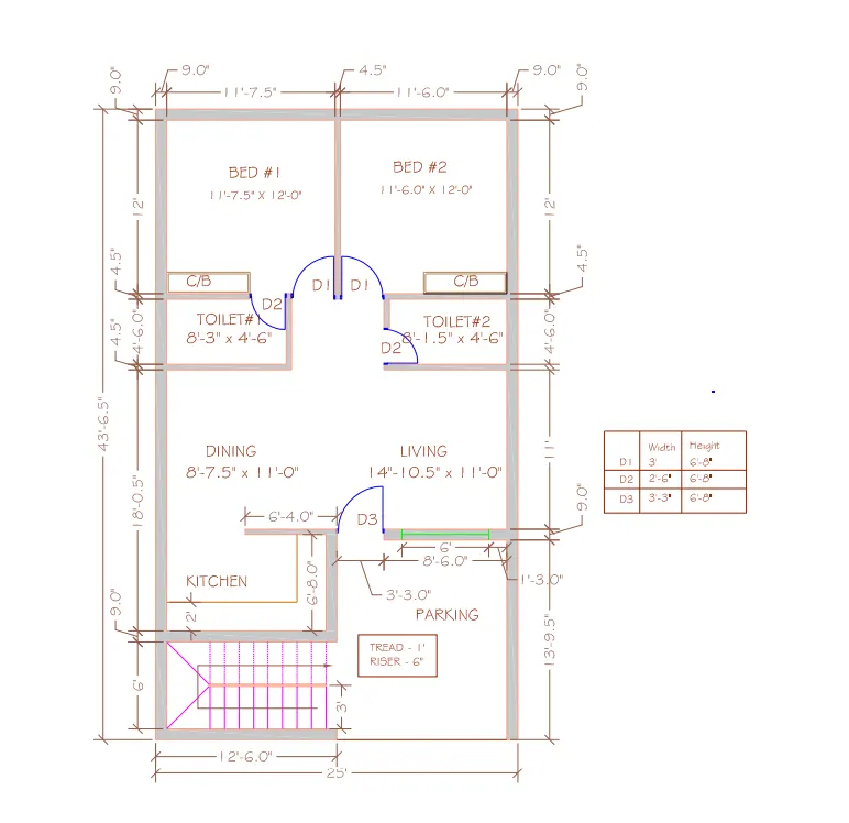
Sketch the layout of a residence as shown in the Figure 1. Consider all dimensions as reference to sketch the unit plan. Also the text in the layout are only for reference. Assume the missing dimensions. Also, refer the schedule for size of the doors.
Aim:
To draw a sketch the layout of a residence as shown in the figure by using the AutoCAD software
Introduction:
We have a some sketches as shown in above. Consider all dimensions as reference to sketch the unit plan. Also the text in the layout are only for reference. Assume the missing dimensions. Also, refer the schedule for size of the doors.
Procedure:
Step-01: Switch on the software and set the units
- First of all switch on the AutoCAD 2023 software and set the units for sketch the drawing
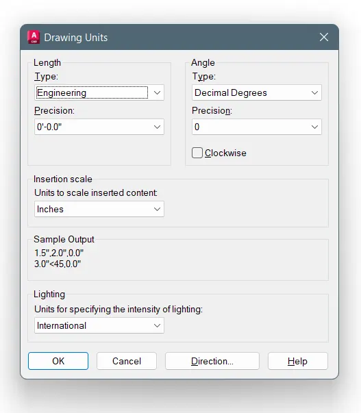
- Then, open the unit dialogue box using the shortcut of UN. It represents units
- Give the type of length is Engineering
- Precision is 0'-0.0"
- And the isertition scale is Inches as shown in below
Step-02: To switch ON the Drafting Settings
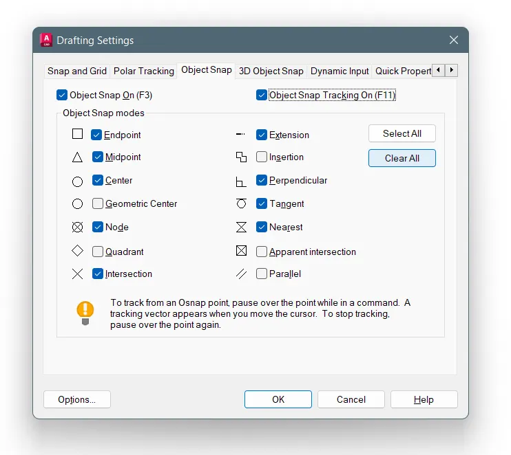
- To switch ON the drafting settings in the shortcut of DS and open the dialogue box as shown in below
- ON the Object Snap and Object Snap Tracking or using the shortcut of F3 and F11
- Switch on Endpoint, Midpoint, Center, Node, Intersection, Extension, Perpendicular, Tangent and the Nearest. These object snaps are used to sketch this drawing
Step-03: Edit the screen
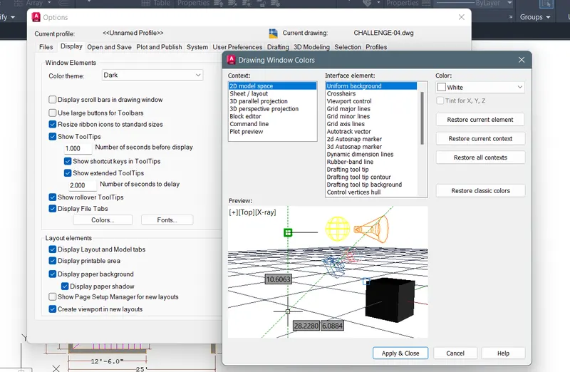
- Edit my AutoCAD software screen is white color as the procedure of
- Open the Option Tab using the OP shortcut
- And click the Colors botton and then, switch to white color as shown in below figure
Step-04: To draw the sketch
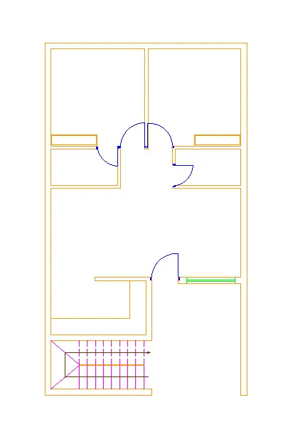
Step-4.1: Draw the floor plan
- Refer the given floor plan and take the measurements from the drawing
- The size of the built up area is 25' x 43'-6.5"
- And start sketch the drawing in the software
- Draw a line using Line command L
- And change the line color using the Bylayer in Properties tab as given in the question drawing
- The colors of lines are Orange, Blue, Pink and green
Step-4.2: Give the names as given in sketch
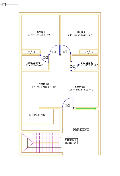
- The names of the parts of the building is already given in question drawing
- The names are given as shown in below figure
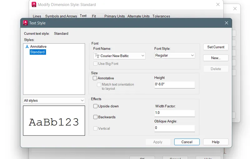
c. Take Text Style from the Dimstyle command and
d. Take the font size is 8.0" and the font name is Courier New Baltic
e. And type MText in command box and then, click the cursor anywhere i want
f. And then, give the names as given in the drawing
Step-4.3: Mark the measurements
- The measurements are marking as given in the sketch
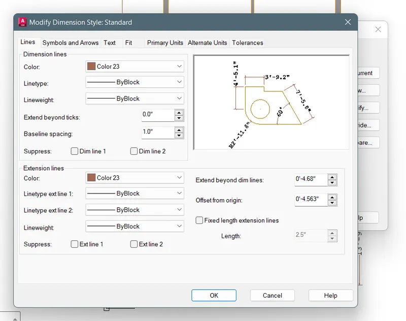
- First type Dimstyle and select modify
- In line tab select the line color is Color 23 in Dimension lines and Extension lines
- And then, increase the Baseline spacing 1" and Extend beyond din lines 4.68", Offset from origin 4.563"
- As shown in figure
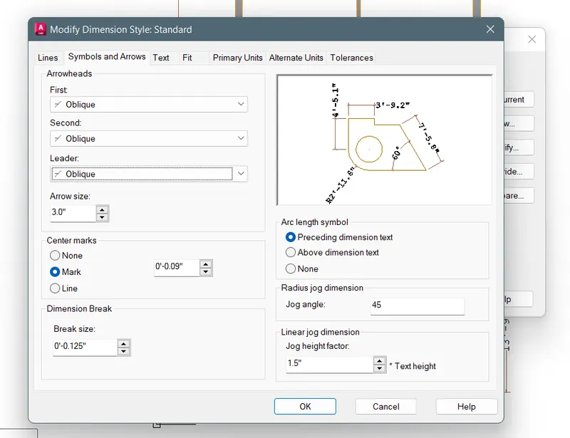
- Select Symbols and Arrows Tab and change the Arrowheads to Oblique
- The Arrow size is 3" and breaking size is 0.125"
- As in the figure
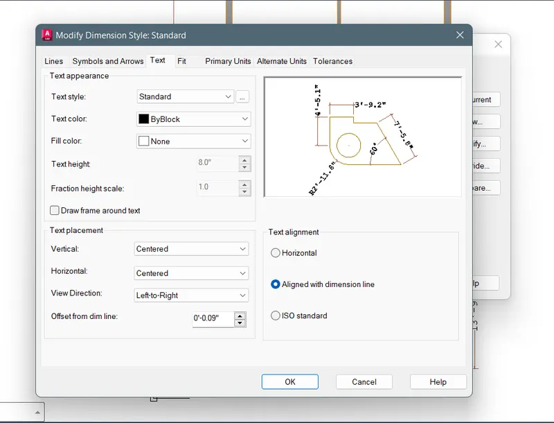
- Select Text Tab as given in text height is 8"
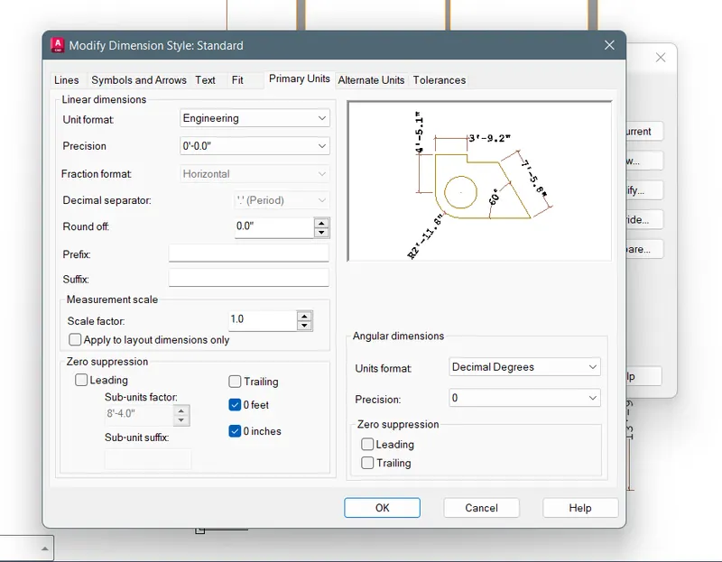
- Select Primary Units and give the Unit format is Engineering
- Precision in 0'-0.0"
- And then, select OK and then, setcurrent and click Close
- Select in dimesion tab and click Linear
- And then, select the points where in the dimesions are i want and drag the dimension line
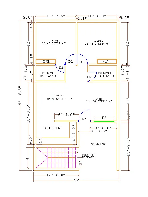
Step-4.4: Give the Hatch for walls
- Type the BH it represents the Hatching for the drawing
- And select the Solid from the Hatch bar
- Then, Pick the section of the wall as given in below figure
- And then, change the color of hatch is 147.149.152 it is brown color
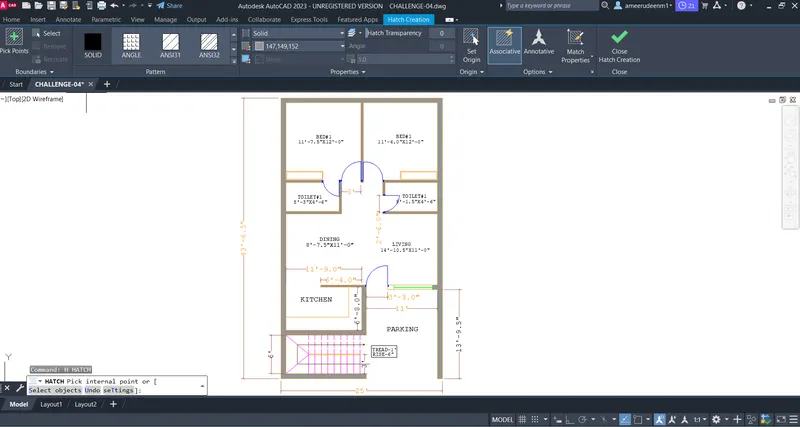
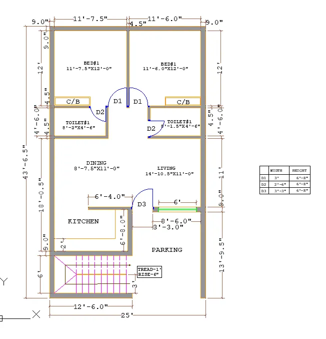
- Finally screenshot the all drawings using the Window key+Shift+S
- It is Snipping Tool in computer
- And then, upload the figures
Result:
The drawing of the given sketch of residence floor plan is completed using the AutoCAD 2023 software
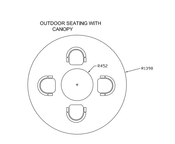
2. Sketch the seating plan for an outdoor canopy. Assume the dimensions for the seating. Also, consider the dimensions in mm.
Aim:
To draw sketch the seating plan for an outdoor canopy.
Introduction:
The drawing of sketch the seating plan for an outdoor canopy. Assume the dimensions for the seating. Also, consider the dimensions in mm.
Procedure:
Step-01: Switch on the software and set the units
- First of all switch on the AutoCAD 2023 software and set the units for sketch the drawing
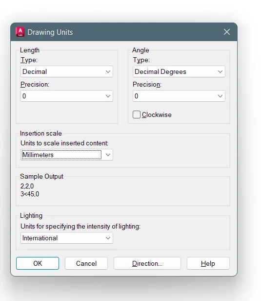
- Then, open the unit dialogue box using the shortcut of UN. It represents units
- Give the type of length is Decimal
- Precision is 0
- And the isertition scale is Millimeters as shown in below
Step-02: To switch ON the Drafting Settings
- To switch ON the drafting settings in the shortcut of DS and open the dialogue box as shown in below
- ON the Object Snap and Object Snap Tracking or using the shortcut of F3 and F11
- Switch on Endpoint, Midpoint, Center, Node, Intersection, Extension, Perpendicular, Tangent and the Nearest. These object snaps are used to sketch this drawing
Step-03: To setting up the dimestion style
Step-3.1: Symbols and Arrows
- Type Dimstyle in command box and select modify
- And then, click Symbols and Arrows
- Give the Arrow size is 40.18 as shown in below
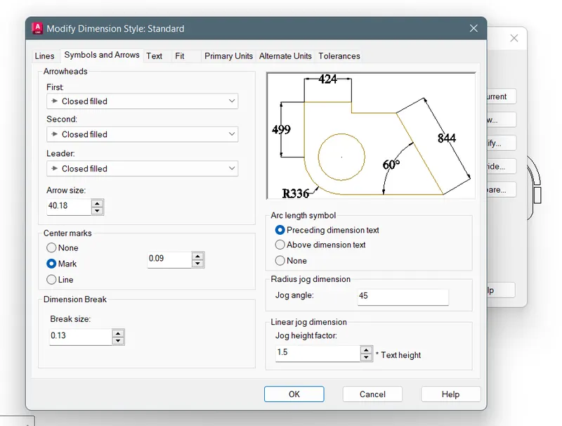
Step-3.2: Text
- Then, select Text tab and give the text height is 75.18
- Text details are as shown in figure
- And then, mark the dimesions
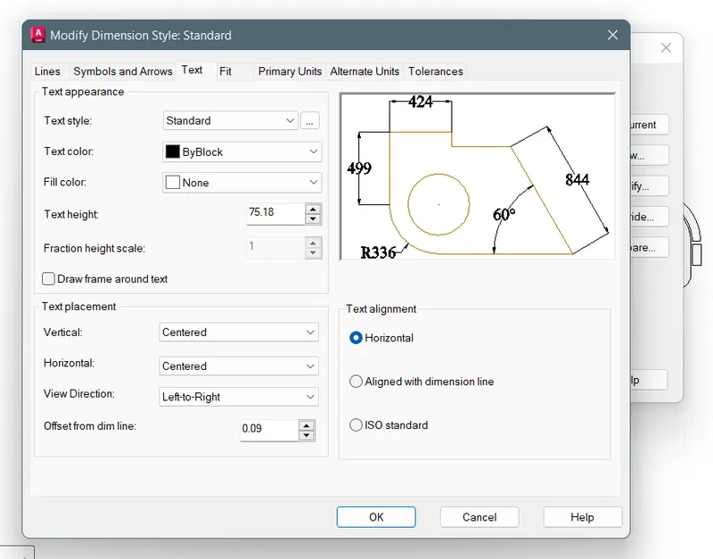
Step-04: Text style
- Through that above process this Text style is selected from the dimstyle dialogue box
- The text height is 50
- And then, click Apply and setcurrent and then, close
- The process as shown in figure
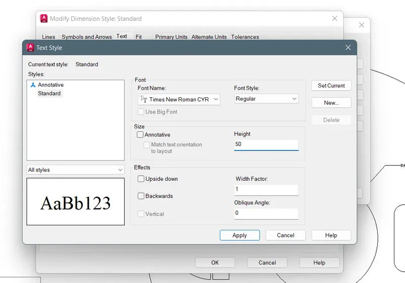
Step-05: To draw the sketch
Step-5.1: Draw the outdoor seating with conopy
- Refer the given outdoor seating with conopy drawing
- The size of the seating is R1398 is outer circle radius and R452 is inner circle radius
- And start sketch the drawing in the software
- Draw a line using Circle command C
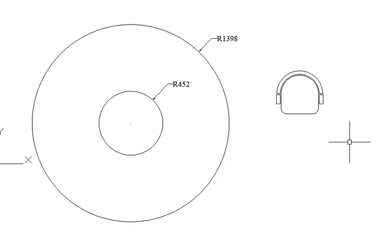
Step-5.2: Draw the seating
- Draw the conopy using the Line command L
- Assume the dimesions of the seating
- Make the square box and draw a Arc (3-Point)
- And Offset the Arc
- And then, make the rectangle below the Arc
- This drawing make as a given sketch
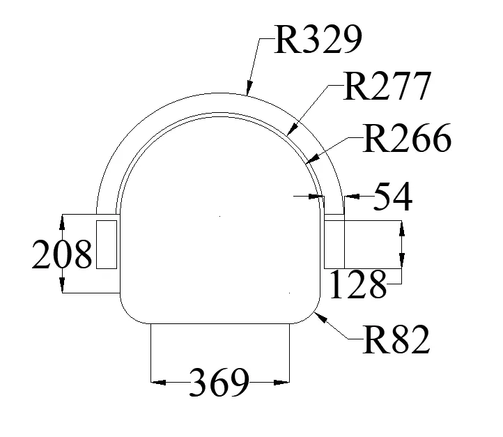
- And then, using the Fillet command for smooth finish R100
- Scale this drawing and drag to the circle
- The dimesions of the seating as shown in below
Step-06: Finish the model
- Copying the seating using the command of Copy (C)
- Mirror (MI) the seating to the both sides from the centre of the inner circle
- Using the text command for the skektch topic is MText
- And select the cursor and give a name of the drawing
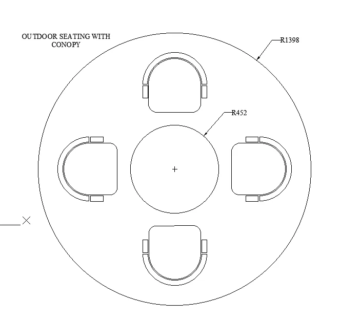
- Finally screenshot the all drawings using the Window key+Shift+S
- It is Snipping Tool in computer
- And then, upload the figures
Result:
The drawing of the given sketch of outdoor seating with conopy is completed using the AutoCAD 2023 software. Used the given dimesions form the question for draw this sketch
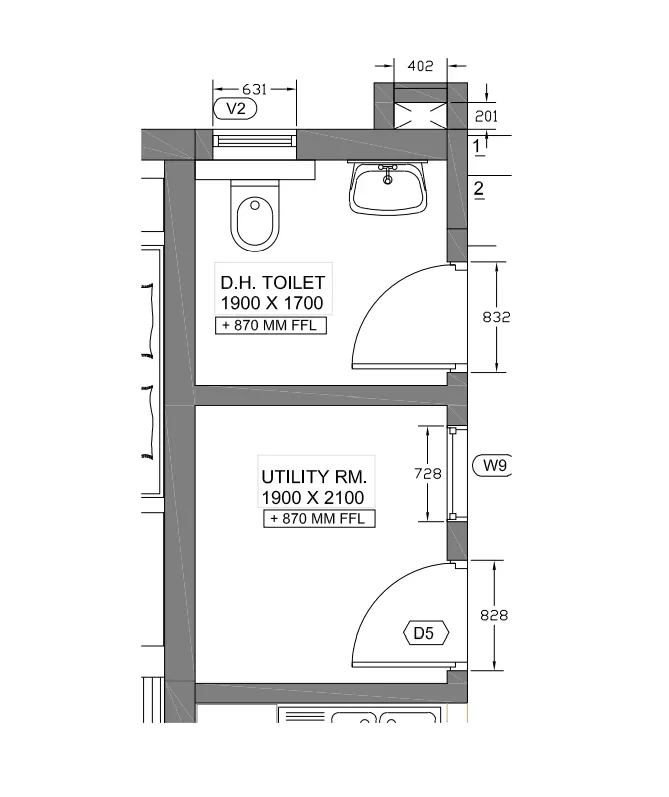
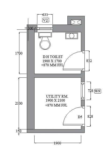
3. Sketch the part plan for the toilers and utilities room. Consider the outer wall thickness as 300mm and inner wall thickness as 150mm. Also, assume the missing dimension, Texts, dimensions, and hatches are only for references. Also, symbols for toilets and w/c are also for references.
Aim:
To sketch the part plan for the toilet and utilities room using the AutoCAD 2023 software.
Introduction:
Sketch the part plan for the toilers and utilities room. Consider the outer wall thickness as 300mm and inner wall thickness as 150mm. Also, assume the missing dimension, Texts, dimensions, and hatches are only for references. Also, symbols for toilets and w/c are also for references.
Procedure:
Step-01: Switch on the software and set the units
- First of all switch on the AutoCAD 2023 software and set the units for sketch the drawing
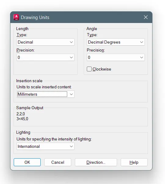
- Then, open the unit dialogue box using the shortcut of UN. It represents units
- Give the type of length is Decimal
- Precision is 0
- And the isertition scale is Millimeters as shown in below
Step-02: To switch ON the Drafting Settings
- To switch ON the drafting settings in the shortcut of DS and open the dialogue box as shown in below
- ON the Object Snap and Object Snap Tracking or using the shortcut of F3 and F11
- Switch on Endpoint, Midpoint, Center, Node, Intersection, Extension, Perpendicular, Tangent and the Nearest. These object snaps are used to sketch this drawing
Step-03: To setting up the dimestion style
Step-3.1: Symbols and Arrows
- Type Dimstyle in command box and select modify
- And then, click Symbols and Arrows
- Give the Arrow size is 50.18 as shown in below
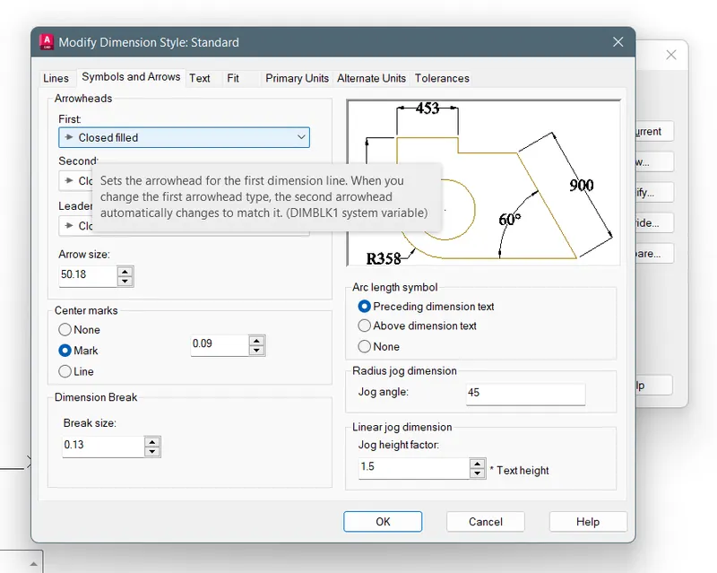
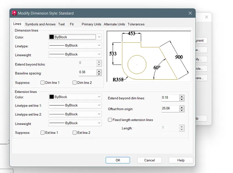
Step-3.2: Lines
- Then, select Line tab and increase the offset from the origin is 25.06
- Baseline spacing is 0.38
- Line details are as shown in figure
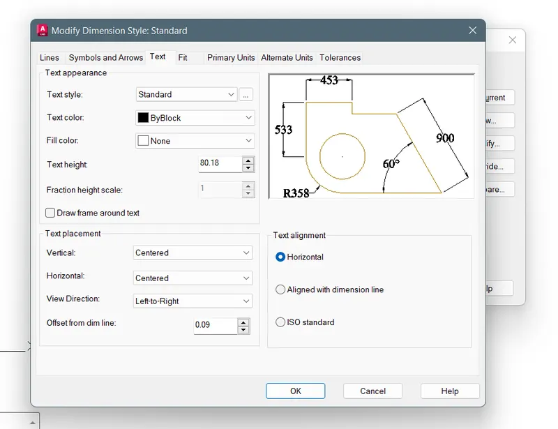
Step-3.3: Text
- Through that above process this Text is selected from the dimstyle dialogue box
- Increase the text height is 80.18
- And then, click Apply and setcurrent and then, close
- The process as shown in figure
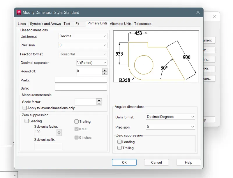
Step-3.4: Primary units
- Slect the primary units tab and the unit format is Decimal
- The precision is 0
- Using these values and mark the dimesions as in the given question drawing
Step-04: To draw a sketch
Step-4.1: Line drawing
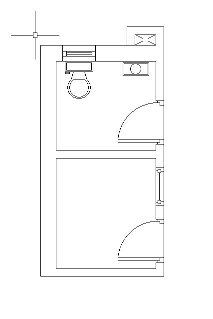
- Draw the line sketch using Line command as given dimesions in question
- And fix the Toilet metric from the Tool Pallete
- Draw the window and doors drawn as given dimesions
Step-4.2: Marking the dimesions and texting
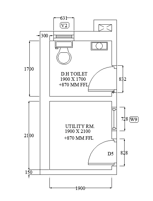
- Using the DIM command for marking the dimesions where i want in this drawing
- Using the MText command for text the parts of the building
Step-4.3: Hatching
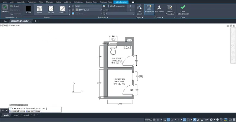
- The hatching for the all around walls in this drawing
- The command is BH for Hatch
- Type the BH in command box and select Solid
- And then, give the hatch color is brown
- Pick the point of giving hatch
Step-05: Finishing the model
- Finally screenshot the all drawings using the Window key+Shift+S
- It is Snipping Tool in computer
- And then, upload the figures
Result:
The sketch of part plan for the toilet and utilities room using the AutoCAD 2023 software is finished using the above process and the dimesions of the building drawing is reffered as in given question.