Creating a Residence Layout, Seating plan, Toilet and Utility room plan using AutoCad
Creating a Residence Layout, Seating Plan, Toilet and Utility room plan using AutoCad.
1.Residence Plan:
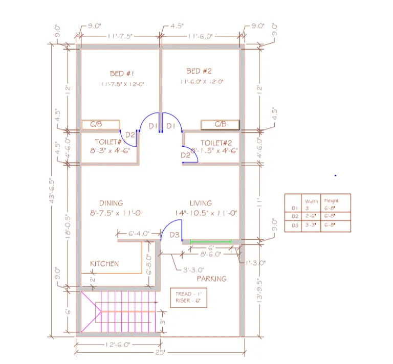
AIM:To Sketch the layout of a Residence as Shown in the figure above in the AutoCad.
Introduction: The Desired plan is Created in AutoCad using primarily the Construction line tool. The Procedure of Drawing is explained in detail with diagrams of each step and the final result is given.
PROCEDURE:
First I Selected UNITS and LIMITS , DIMENSION STYLE as per Given Question Format.
In the Command Prompt write L Enter.
Specify the First Point as (0,0) have taken this as my first point.
- I drawn all lines with xy Co-ordinates dimensions like this (x,y).
- I Changed the DIMSTYLE for inches feet format, I Selected the engineering dimensions.
- Doors and Windows Blocks maked by own in AutoCad.
- In the Command prompt write all dimensions for to draw this drawing like above co-ordinates enter.
- I used TRIM, OFFSET, EXTEND Commands to draw this Drawing.
- I Used HATCH Command in tool palettes for Wall Masonry indication in drawings with sufficient dimensions to clear visible.
- I used table Command for entry of door details.
- I Changed the Dimensions lines ,text Colours for to Clear Visible of Drawing.
- I used DIMLINEAR,ALIGNED, ANGULAR Commands to measure the all dimensions in the drawing.
- I used MULTILINE TEXT to Write titles on Drawing.
- I Changed the line properties for Colours as per drawing.
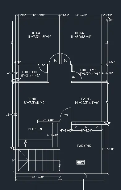
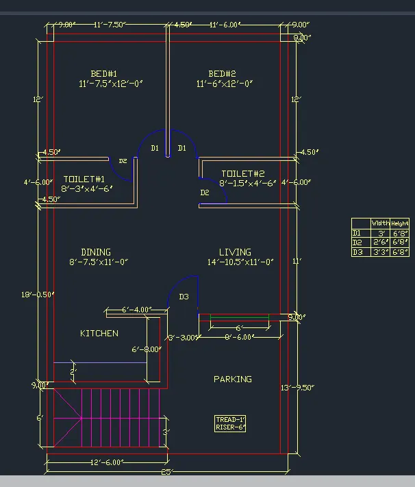
RESULT:
2. SEATING PLAN FOR AN OUTDOOR CANOPY:
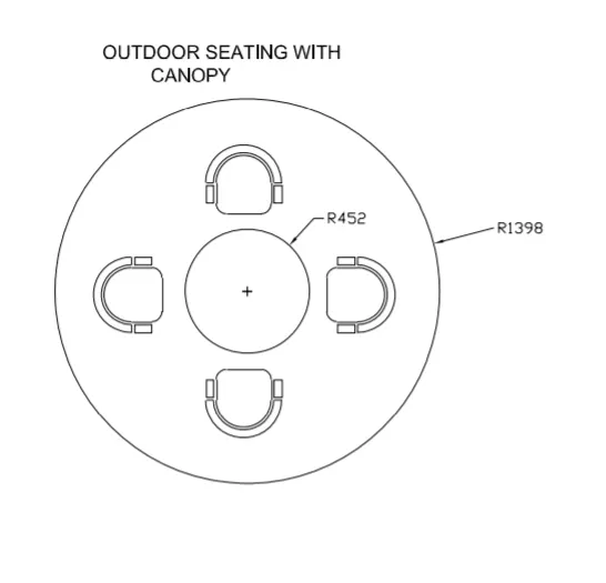
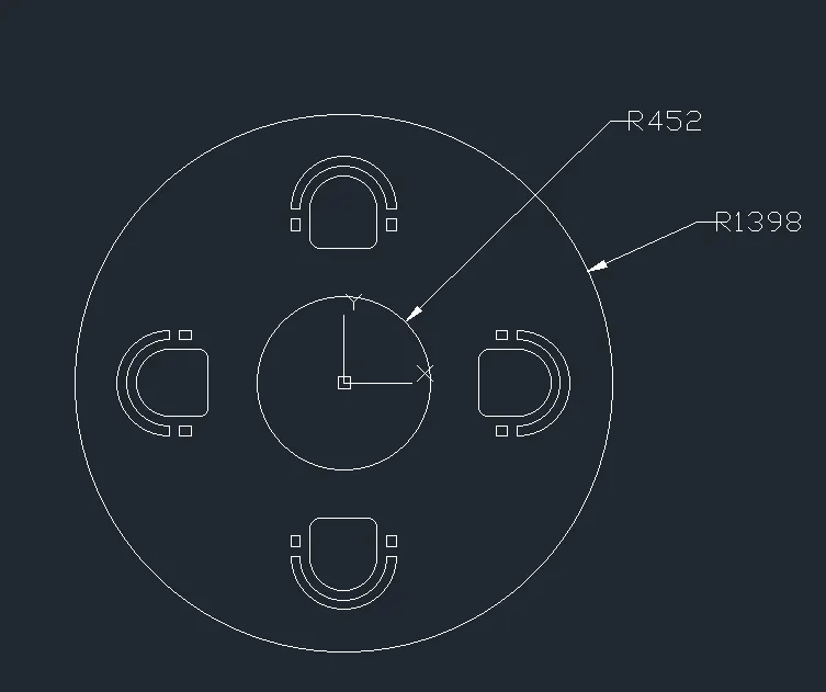
AIM: To Sketch the Seating plan for an outdoor canopy as shown in the figure above in AutoCad.
INTRODUCTION: The Desired Plan is Created in AutoCad using primarily the line ,Circle and Arc tools.The Procedure of Drawing is explained in detail with diagrams of each step and the final result is given. The Dimensions for seating are assumed as appropriate.Also, all the dimensions are Considered in mm.
PROCEDURE:
First I Selected UNITS and LIMITS , DIMENSION STYLE as per Given Question Format.
In the Command Prompt write L Enter.
Specify the First Point as (0,0) have taken this as my first point.
- I drawn all lines with xy Co-ordinates dimensions like this (x,y).
- I Changed the DIMSTYLE for milimeters, I Selected the decimal dimensions.
- I used Chamfer to connect the various lines or i drawn that inclined lines with measuring angles for to make the blocks in autocad created by own.
- In the Command prompt write all dimensions for to draw this drawing like above co-ordinates enter.
- I used Snap cursors reference points to set the chairs properly around the table.
- I Used Circle Command to draw the Circle and i Drawn the Centre point of the Circle with given Dimensions.
- I Changed the Dimensions lines ,text Colours for to Clear Visible of Drawing.
- I used DIMLINEAR,ALIGNED, ANGULAR Commands to measure the all dimensions in the drawing.
- I used MULTILINE TEXT to Write titles on Drawing.
- Chair Blocks tool palettes are created by my own Draw.
RESULT:
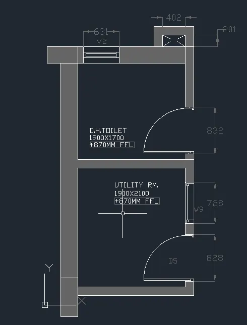
3. Part Plan for the Toilets and Utilities Room:
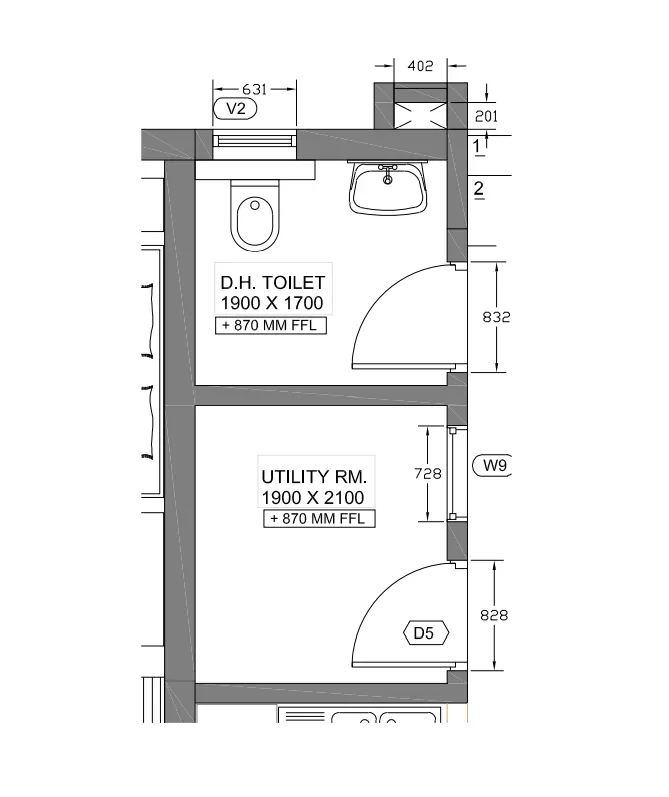
AIM: To Sketch the Part Plan for the Toilets and Utilities Room as shown in the figure above in AutoCad.
INTRODUCTION: The Desired Plan is Created in AutoCad using primarily the Construction line ,Circle and Arc tools.The Procedure of Drawing is explained in detail with diagrams of each step and the final result is given. The outer wall thickness is considered as 300mm and inner wall thickness is considered as 150mm .Also, all the dimensions are Considered in mm.
PROCEDURE:
First I Selected UNITS and LIMITS , DIMENSION STYLE as per Given Question Format.
In the Command Prompt write L Enter.
Specify the First Point as (0,0) have taken this as my first point.
- I drawn all lines with xy Co-ordinates dimensions like this (x,y).
- I Changed the DIMSTYLE for milimeters, I Selected the decimal dimensions.
- Wall thickness are not mentioned in the drawing so i taken 300mm thick for all walls cutouts and external and internal.
- Doors and Windows Blocks maked by own in AutoCad.
- In the Command prompt write all dimensions for to draw this drawing like above co-ordinates enter.
- I used TRIM, OFFSET, EXTEND Commands to draw this Drawing.
- I Used HATCH Command in tool palettes for Wall Masonry indication in drawings with sufficient dimensions to clear visible.
- I used table Command for entry of door details.
- I Changed the Dimensions lines ,text Colours for to Clear Visible of Drawing.
- I used DIMLINEAR,ALIGNED, ANGULAR Commands to measure the all dimensions in the drawing.
- I used MULTILINE TEXT to Write titles on Drawing.
- By Using Design Center Washbasin and EWC is Fixed.
RESULT: