Creating a Layout, Section and Elevation with dimensions using AutoCad
Aim- To create the sections as shown in the figures use proper dimensions using auto cad
Procedure-
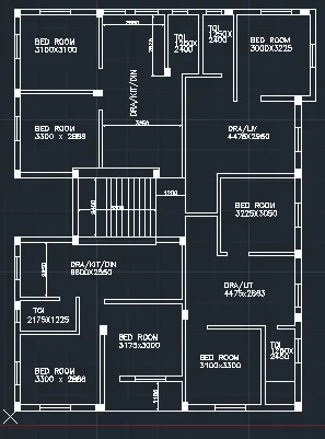
Floor plan
First conver units in millimeters in units command
Zoom enter all enter
Then use XL command and draw one horizontal and one vertical lines
Then trim on the other side which you dont want to draw
Give offset of 230 assuming on the outer walls
Then draw bedroom of using offset of 3300x2888
Then draw toilet of 2275x1225
Then trim the extra ends
Then give inner walls offset of 150 assuming
then draw bedroom and verenda of offset of bedroom of lengths 3170 x 1000 remaining of ver
Inner wall offset of 150mm
Then draw the another bedroom and toilet of 3100x3000 and toi of 1250x2150
Then give outer wall for toilet of 230mm then trim extra ends of XL line of horizontal
Then draw KIT/DRA/DIN of offset of 660x2550
Give outer wall offset 230
Then come from right side of outer wall
Draw offset for KIT/DRA off 4475x2863
With that offset create bedroom of lengths 3225x3050
Then draw the staircase of landings,riser and thread in the given dimensions
Then draw the bedroom from outer wall of lengths 3225x3220
Then draw DRA,KIT, of respected dimensions wrt the bedroom drawn
Then draw two bedrooms in the two corners as given dim
Then draw two toilet as shown
Then Cloase it with the 230 outer wall
Then Give openings of all the door given with trim command
Draw windows and ventilators of respectes places
Give dimensiond and naming to all the rooms using DT command
SECTION- AA
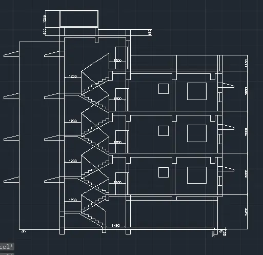
Procedure
First project all the coloums towares down using XL command
Strat frm the ground floor
Draw one line from one corner to other corner for sratting reference
Then give pcc of 200mm of offset
Then give offset of total height of 2450 and give slab thickness of 150 downwards
Give beam sections to downwads
Trim all coloumn in GF hence middle coloumn is not visible
Give staircase section of 143 riser and 300 thread of 7 steps towards and give landing
Continue for another circle
Join railing and stairslab with isometric command
Give window section which is cut at a section
Then give wall projection with just empty line because plane wall and lintel of windows outwards
Then go to the first floor give same projections but give
Door beside coloumn is visible
Then toilet and bedroom window is in the section is visible so draw them
Then all the three coloumns are visible
The the window on the outer wall which is cut is visible so draw it in the wallitself because only side is visible
The following first floor dimensiond is same for second and third floor hence copy and paste it in the second and the third floor
Over head tank is visible and give it in the given dimensions
By using DIMLIN command give dimensions and
By using multileader command give all the specifications
Then bt DT command give all the texts which are necessary
SECTION BB
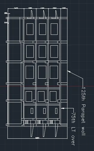
The section is cut at the BB
Then One entire side of the structure is visible
First project all the coloumns towards down in XL command
Draw the reference line at some distand whre all floorrs are adjusted
Come fron the ground floor
Give the pcc of 200mm
Offset first floor height of 2450
Give the beams as shown
Then to the second floor
Four windows and one bathroom ventilator window is visible at the section
Draw all the coloumns as in the section and the beams
There is a ver section give it
The catiliver projection is visible give it
The window lintel of bedroom is visible dra
ALL the remaining floors are same you can copy and paste at second and third floor
There is a parapet wall is on the terrace of length 1000
Uding DIMLIN command give all the dimensions
Use DT enter and give texts
Use multileader command and give all details