Creating a Layout, Section and Elevation with dimensions using AutoCad
Q. 1. Create the Plan and Sections as shown in the Figures. Use proper dimension techniques and dimension styles to document the project. Assume the sizes of the doors and windows as per construction standards. Refer to sections for stair details if required.
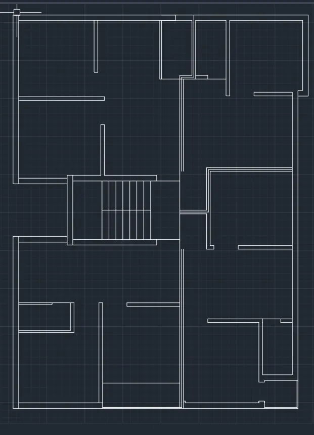
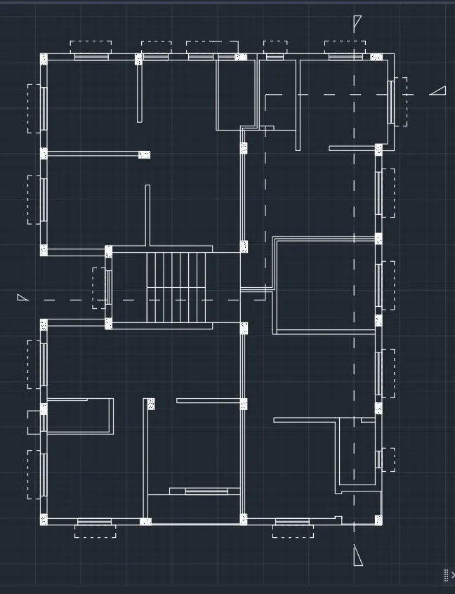
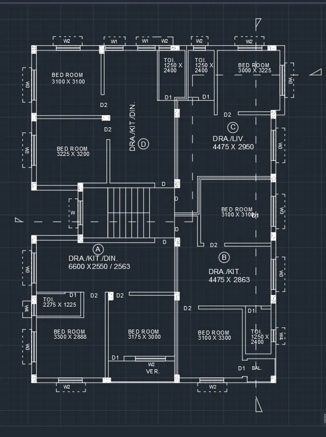
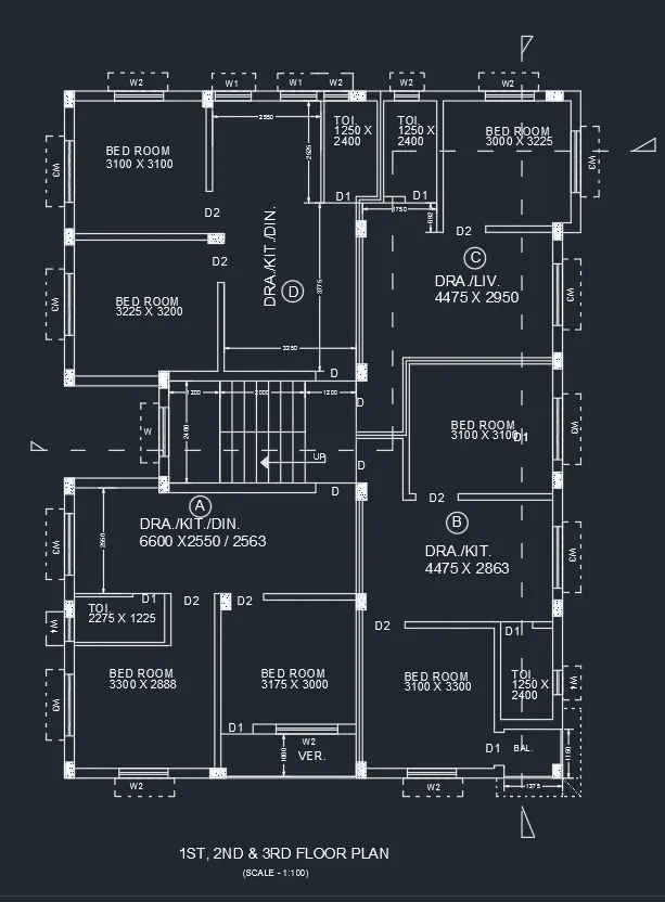
C1 - 1st, 2nd & 3rd FLOOR PLAN
AIM: To create the plan as shown in figure from 1st, 2nd & 3rd floor plan
PROCEDURE:
STEP 1:
- In command prompt type UNITS, set to decimal, precision = 0, insertion scale = millimetres
- In command prompt type LIMAX as (100,100) and LIMITS set to desired
- In command prompt type ZOOM, All and enter
STEP 2: Exterior and interior walls
- In command prompt type XL, to the draft boundary lines
- In command prompt type OFFSET, specify the required distance to get desired lines for drawing
- In command prompt type TRIM, used to remove the space for doors and unwanted lines
- In command prompt type EXTEND, used were to extend is required
STEP 3: Windows, dotted extensions and hatch
- By using commands LINE, REC and OFFSET windows are created
- By using HATCH -> AR SAND is used
 where requried
- By using LT command dotted lines are created

STEP 4: Text
- By using commands DT, TEXTEDIT, SC and MA is used to create text as requried
STEP 5:
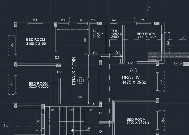
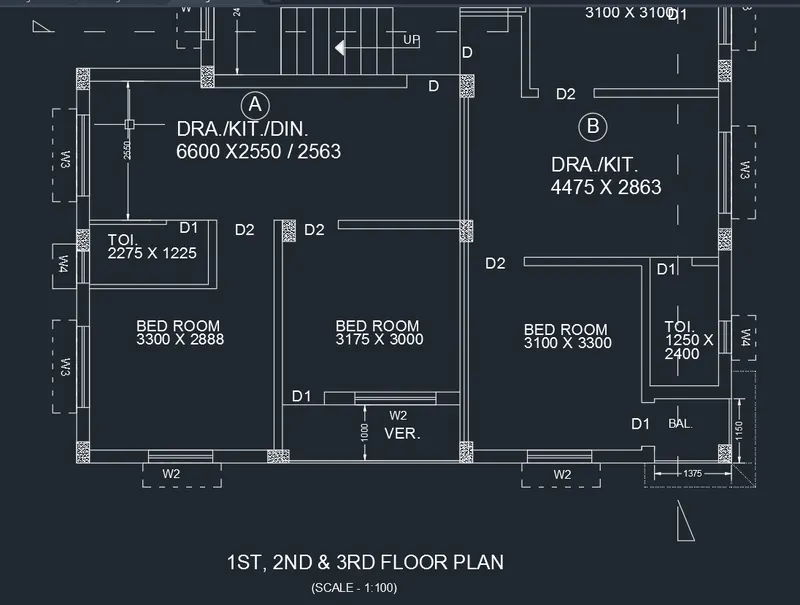
- By using DIMLINEAR command dimensions are done and MLEADER command leader and text created
RESULT:
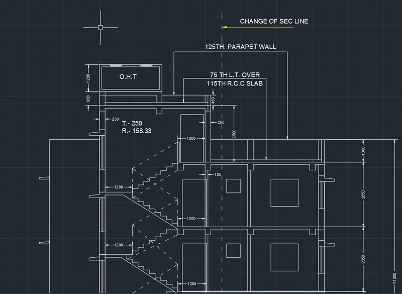
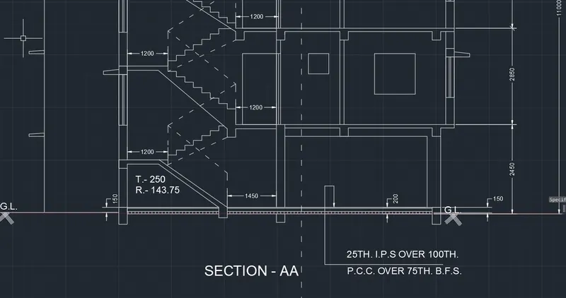
C2 - SECTION - AA
AIM: To create the section - AA as shown in figure
PROCEDURE:
STEP 1:
- In command prompt type UNITS, set to decimal, precision = 0, insertion scale = millimetres
- In command prompt type LIMAX and LIMITS set to desired
- In command prompt type ZOOM, All and enter
STEP 2:
- In command prompt type XL, use Horizantal and Verticle lines for boundary and inner lines
- In command prompt type OFFSET, offset the requried lines as requried
- In command prompt type TRIM, trim of the extra XL lines that are not requried
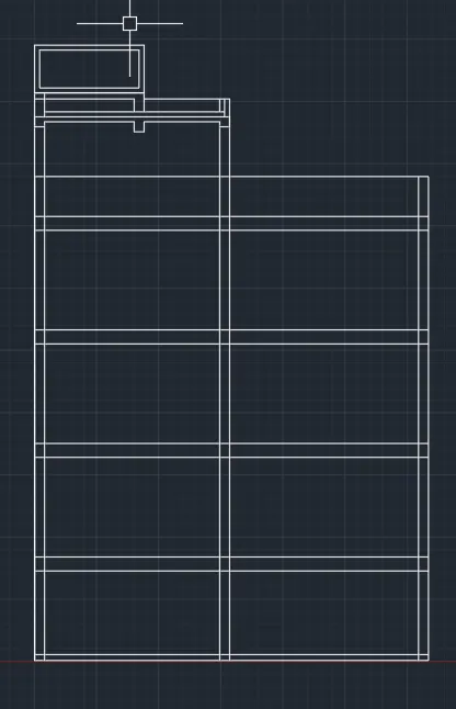
STEP 2:
In command prompt type HATCH, use ACAD-ISO04W100 hatch as requried  At angle of 90 degree
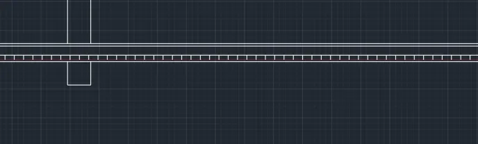
STEP 3:
- By using LT command dotted lines are created
- By using LINE, TRIM, OFFSET, COPY, REC, MOVE commands required lines, sunshades, windows and rectangles are created
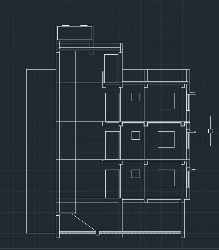
STEP 4:
- By using MATCHDROP, LINE, OFFSET, COPY , TRIM commands stair case is created
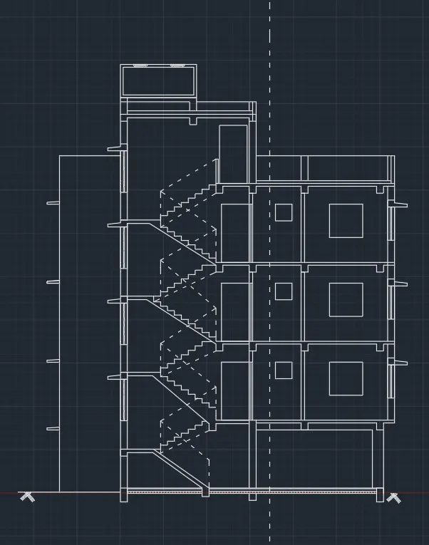
STEP 5:
- By using commands DIMLINEAR, DT and TEXTEDIT, dimensions and texts are assigned
- In command prompt type MLEADER, leaders are used where required
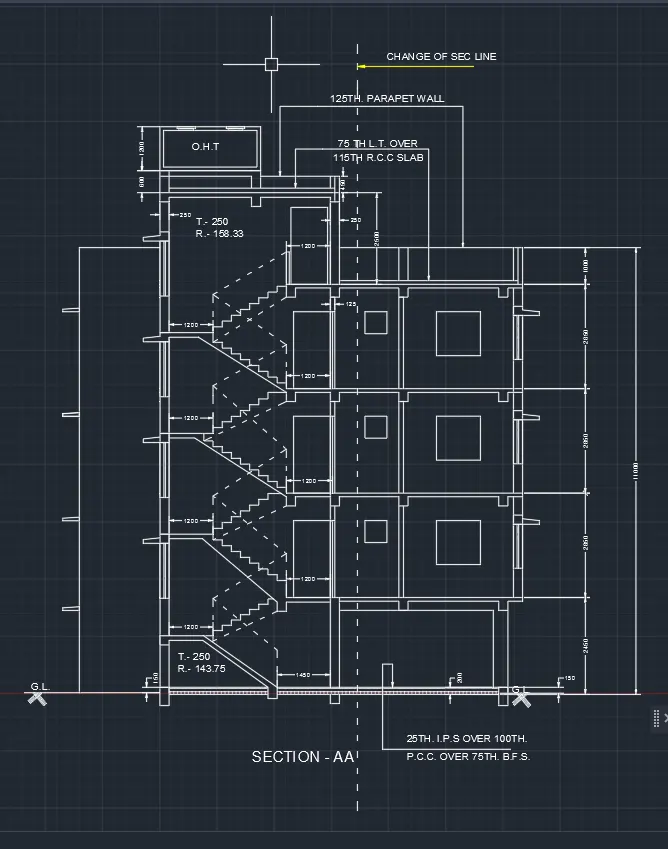
RESULT:
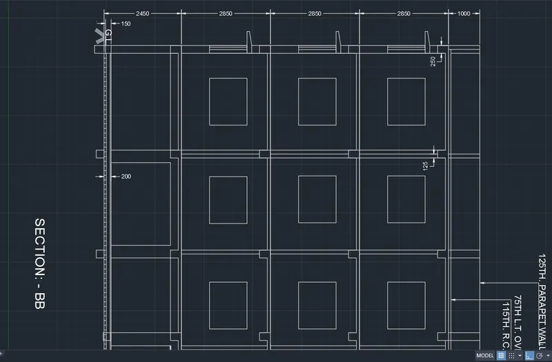
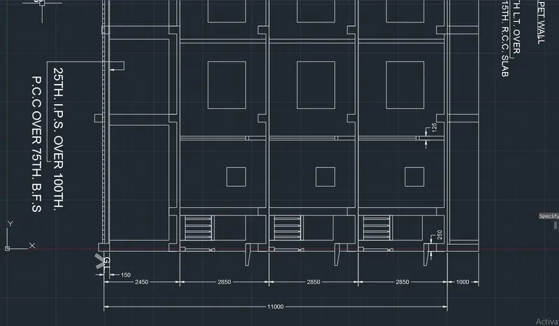
C3 - SECTION - BB
AIM: To create the section - BB as shown in figure
PROCEDURE:
STEP 1:
- In command prompt type UNITS, set to decimal, precision = 0, insertion scale = millimetres
- In command prompt type LIMAX and LIMITS set to desired
- In command prompt type ZOOM, All and enter
STEP 2:
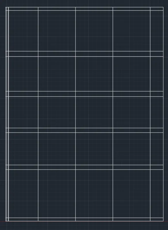
- In command prompt type XL, use Horizantal and Verticle lines for boundary and inner lines
- In command prompt type OFFSET, offset the requried lines as requried
- In command prompt type TRIM, trim of the extra XL lines that are not requried
STEP 2:
- By using TRIM, LINE, COPY, OFFSET, MOVE commands lines in drawing arranged as requried
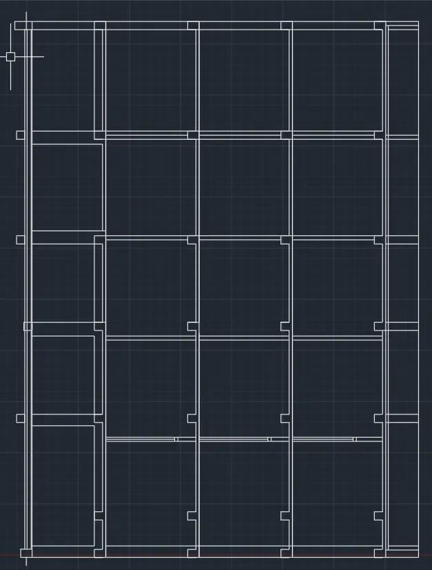
STEP 3:
- In command prompt type HATCH, use ACAD-ISO04W100 hatch as requried
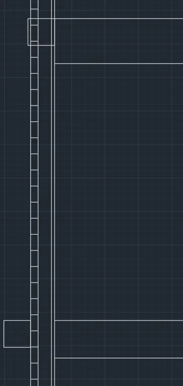
- By using REC, MOVE, COPY commands rectangles are created and aligned as requried also some elements also created by those commands
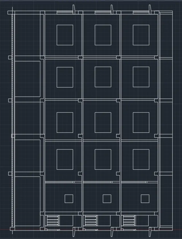
STEP 4:
- By using commands DIMLINEAR, DT and TEXTEDIT, dimensions and texts are assigned
- In command prompt type MLEADER, leaders are used where required
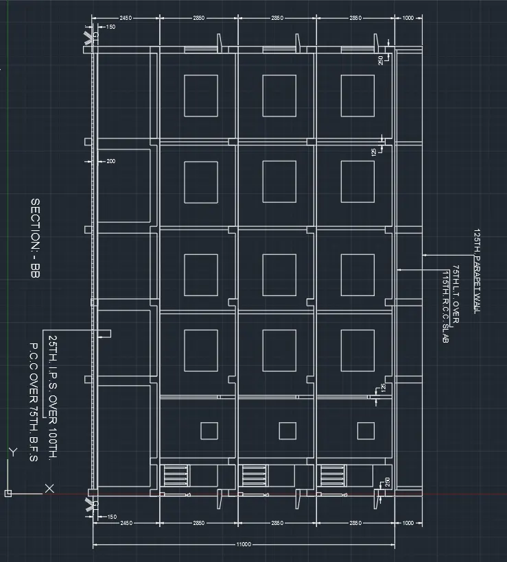
RESULT: