Creating a Layout, Section and Elevation with dimensions using AutoCad
Name: Allan Bryan Jayson Cruz
Course: Master’s Certification Program in High-Rise Building Design & Analysis
Date: October 31, 2021
Creating a Layout, Section and Elevation with dimensions using AutoCAD
CHALLENGE
********************************************************
1. Aim & Introduction
***************
Question
Create the Plan and Sections as shown in the Figures. Use proper dimension techniques and dimension styles to document the project. Assume the sizes of the doors and windows as per construction standards. Refer to sections for stair details if required.
Aim
This challenge aims to provide an experience to the student in sketching a full plan and elevation of a building. This will allow the student to utilize all the AutoCAD tools in multiple uses. The AutoCAD software provides different tools that when utilized together can form any sketch that flows in the imagination. A building part of the civil engineering industry and this correlates the AutoCAD software with the Civil Engineering industry. This challenge aims to give the student deeper understanding on how to utilize the AutoCAD software in sketching a residentail building house.
Introduction
The AutoCAD software provides different tools. The tools used in this challenge is as described below:
Line - creates line object.
Polyline - creates connected line object.
Rectangle - creates rectangle object.
Circle - create circle object.
Trim - Cut unwanted lines or shapes with the provided cutting edges.
Extend - Extend lines to opposite corners.
Move - Move objects to particular locations.
Copy - Copy objects to particular locations.
Rotate - Rotate selected objects to a particular angle with respect to base point.
Array - Copy an object in a set path linearly or polarly.
Join – Joins separated line objects into one object. Line to polyline.
Dimlinear (DLI) - Provides vertical or horizontal linear/straight dimensions.
Dimaligned (DAL) - Provides aligned dimensions.
Dimangular (DAN) – Provides angular dimensions.
Quickdimension (QDIM) – Provides quick dimension of a geometry.
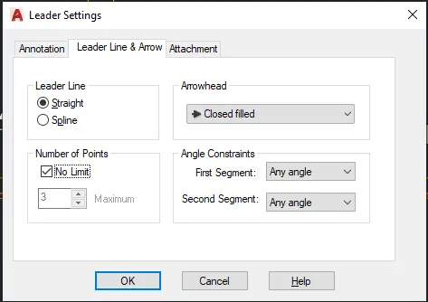
Leader - Creates an arrowhead line.
Layers - Provide identification of line or object groups by their properties.
Units - Open "Drawing Units" window to specify the drawings units.
Dimstyle - Open "Dimension Style Manager" window to modify the dimension properties.
Hatch - Provides hatching pattern in a given object or internal point.
Layer - Open the layer tab which manages the line properties in a drawing.
********************************************************
2. Sketch and Procedure
***************
A. 1ST,2ND, & 3rd Floor Plan
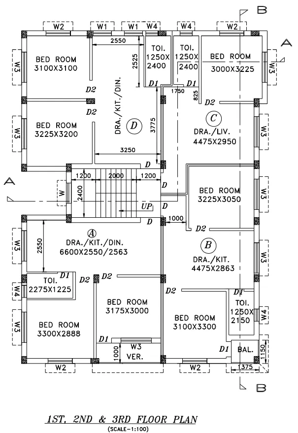
PROCEDURE:
- Create the boundaries using XLINE command.

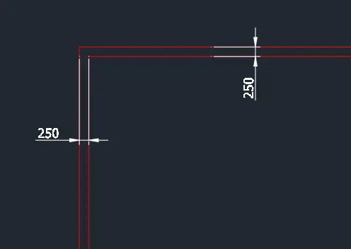
- Cut the lines using trim tool and offset by 250 for the walls.
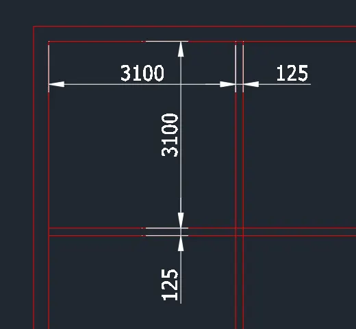
- Sketch the Bedroom. Use offset command and Trim to make the lines.
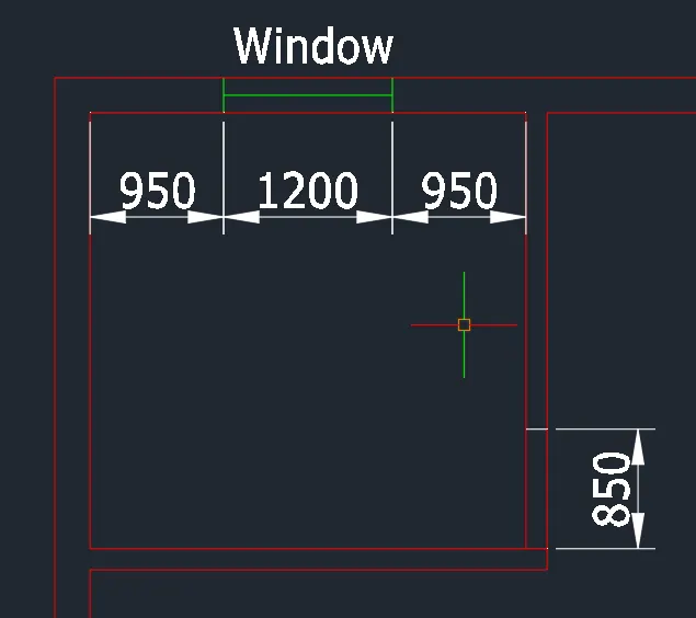
- Create the opening boundary and window designation.
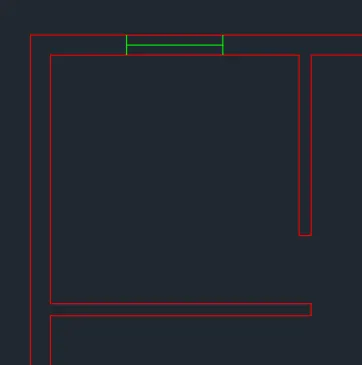
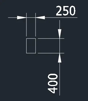
- Add the column designation. Column dimension is 250x400.
To sketch the column. Use rectangle tool and hatch the object using the AR-CONC pattern.
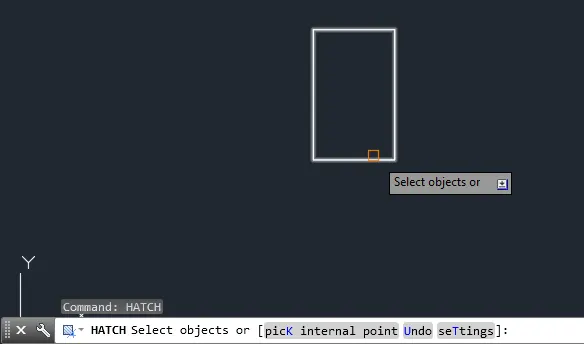
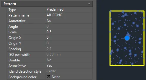
- Apply the CTRL+C and CTRL+V function to create object as block.
- Use move and copy tool to move the column object around the sketch. Copy the column object where it is required. Use rotate tool in cases the column is in horizontal form.
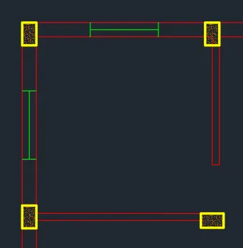
- Proceed with the sketch of the Bed room below. Use offset command and trim tool.
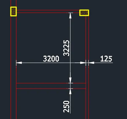
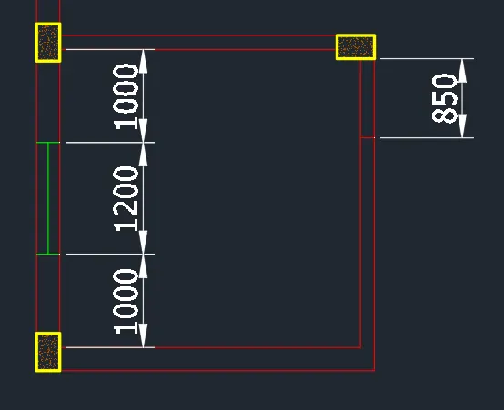
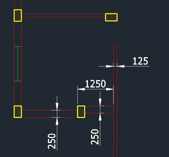
- Proceed with the sketch of DRA./KIT./DIN.. Mind the last Bedroom space as it will be adjusted later for stair space.
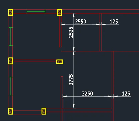
- Use trim tool to delete the unnecessary lines.
- Create the windows. Length is 850.
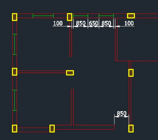
- Proceed with the sketch of the toilet. Use the same procedures and tools to sketch.
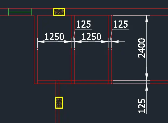
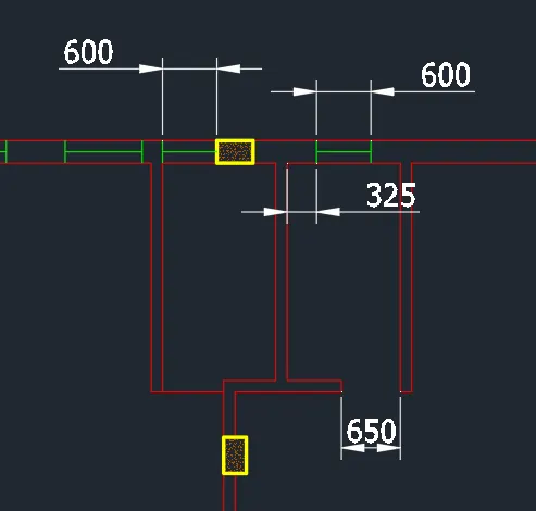
- After sketching the 2 toilets, proceed with the Bedroom.
- Stretch the created wall for easier procedure.
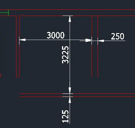
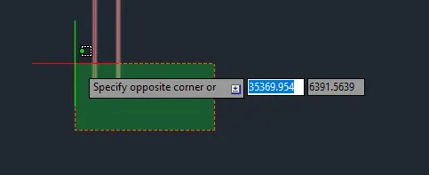
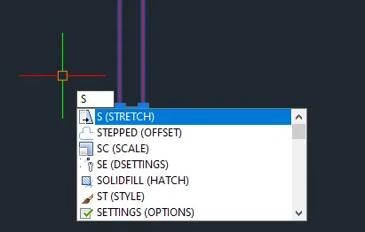
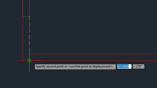
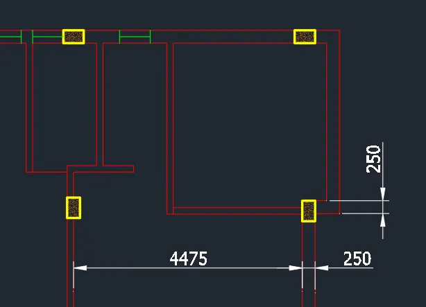
- Add the doors and windows.
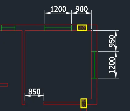
- Sketch the DRA./LIV. and Bed Room below. Mind the hallway leading to the stairs.
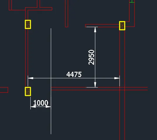
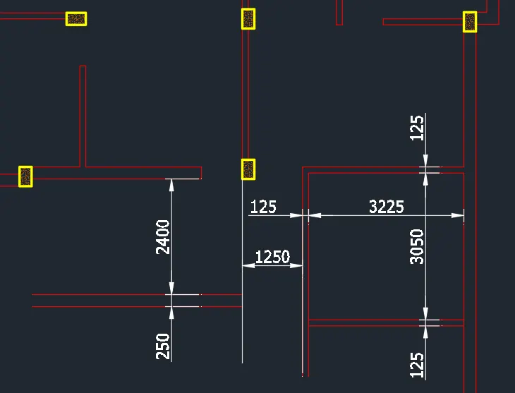
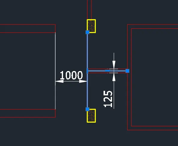
- Continue sketching the stairs.
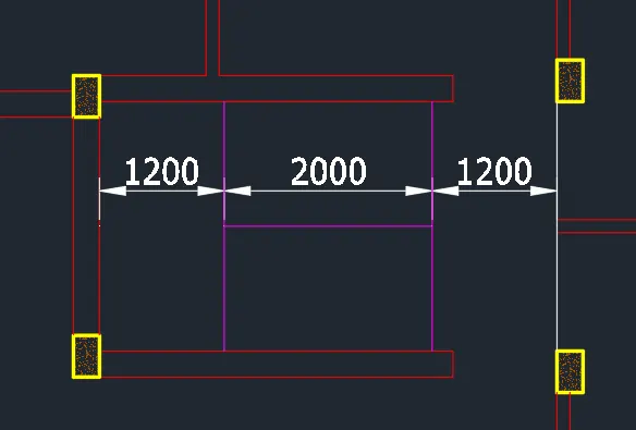
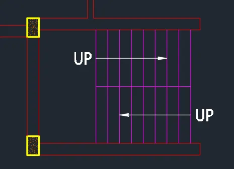
- Now draw the boundaries for the other rooms. Note that the dimensions in each room are connected to each other. Outer walls are measured 250mm and inside walls are 125mm. Use Offset tool, extend tool, line tool, copy tool, and move tool to create the boundaries.
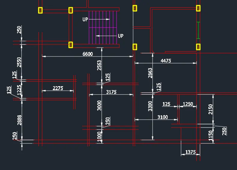
- Use fillet tool and trim tool to create the edges.
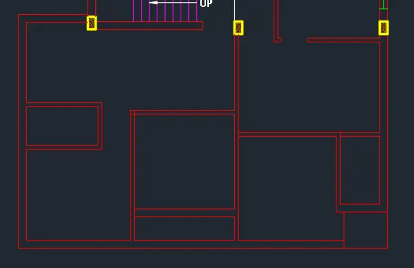
- Once the boundaries are done, proceed the sketch one by one. Complete the room below the stairs. Include the windows and column designations.
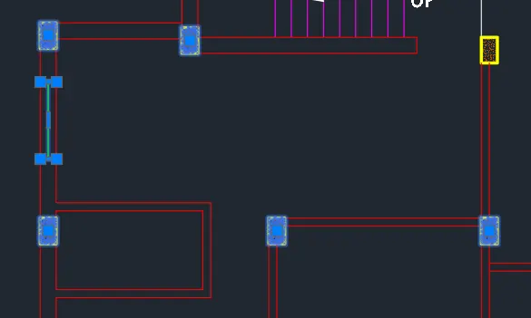
- Continue with the toilet and bedroom. Sketch the Columns and windows. Provide door openings.
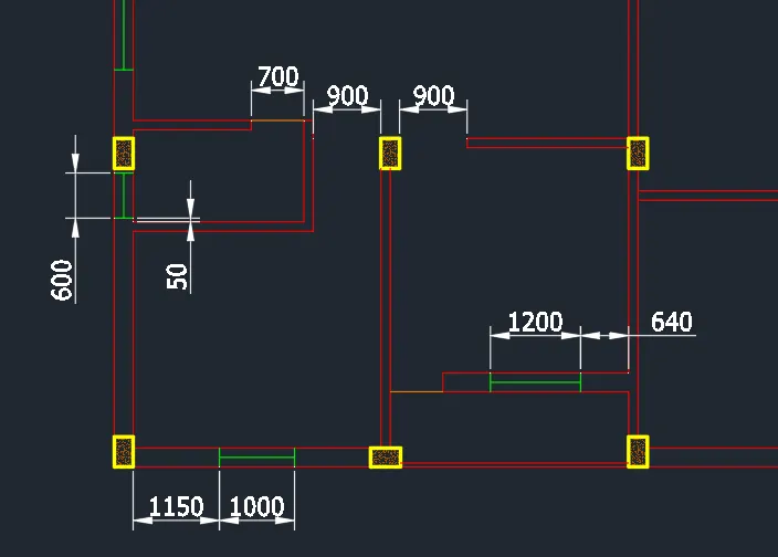
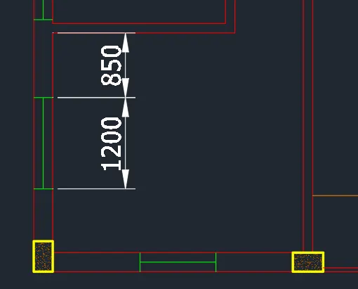
- Once finished, proceed the other side.
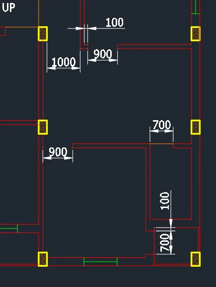
- Complete the windows then sketch the canopy on the outside. Use Hidden lines for their linetype.
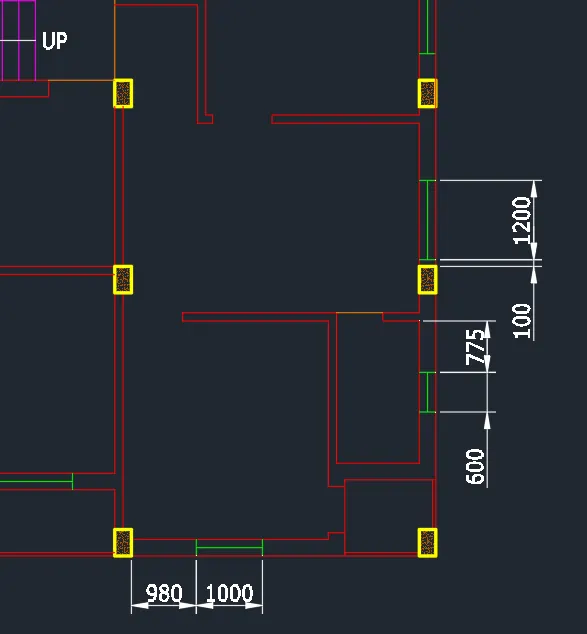
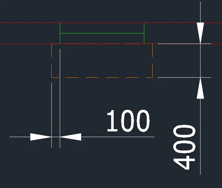
- Do this to designate all the canopies.
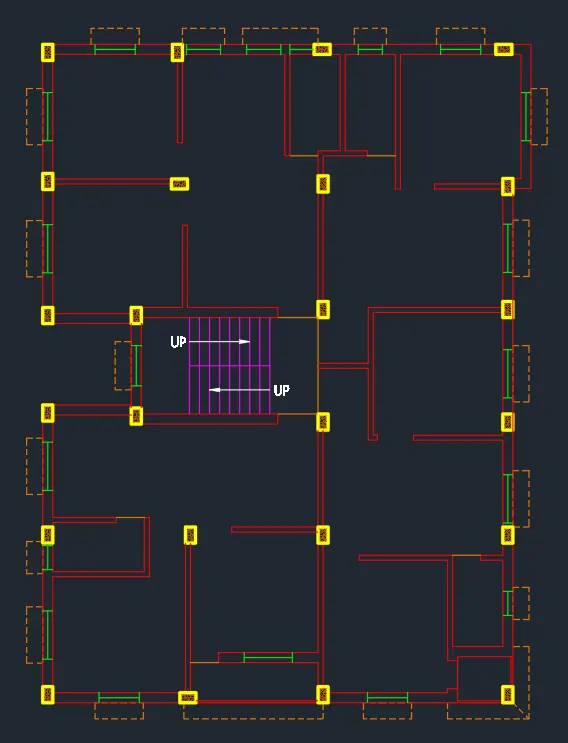
- Provide the dimension and text required in the drawing.
- Use dimlinear to provide dimension and utilize dimcontinue for better progress.
- Apply dimension breaks in places required.
- Use dtext command to provide the texts. Text height is 250mm.
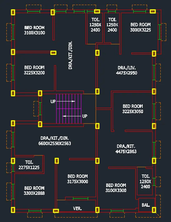
- Add the text designations for the doors and windows.
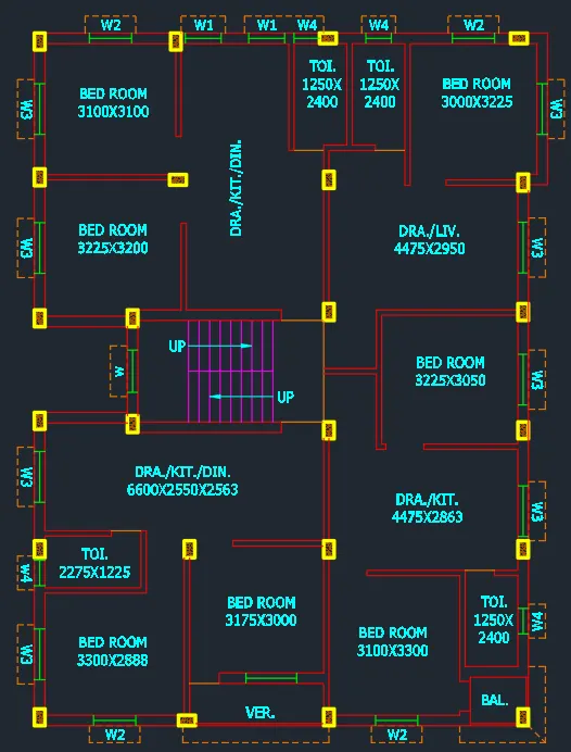
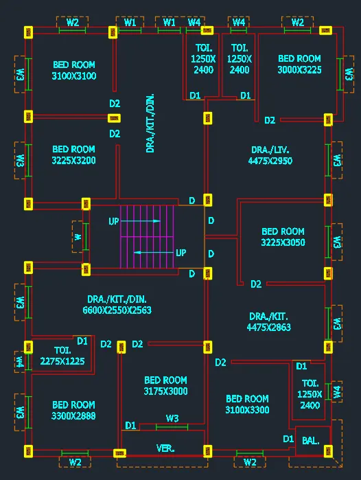
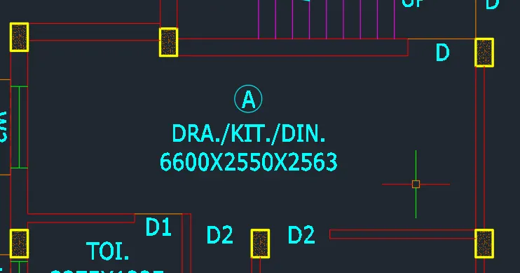
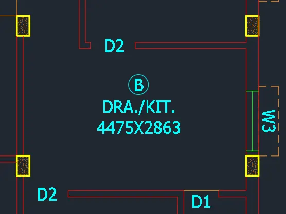
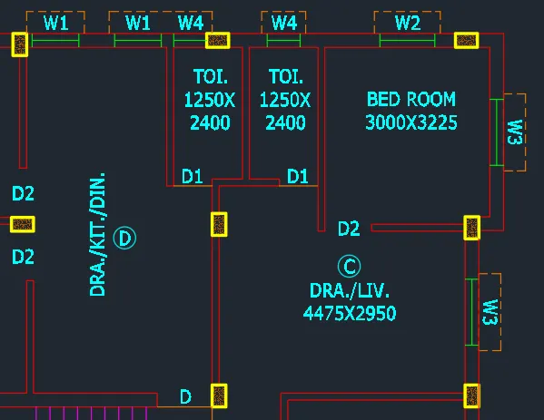
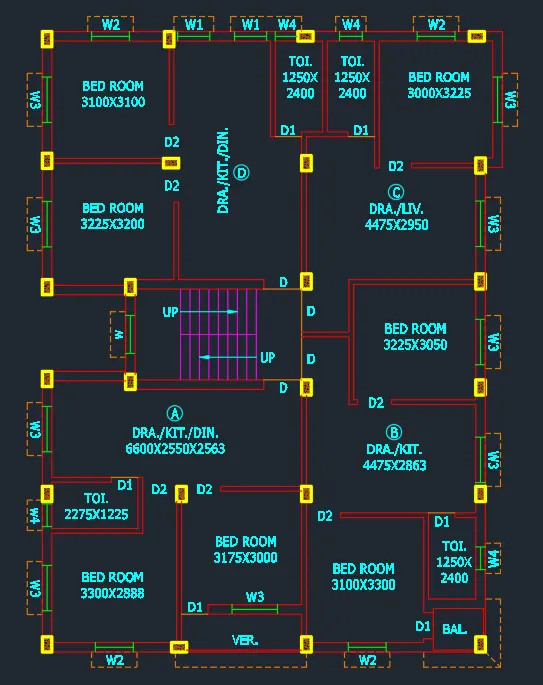
- Now add the dimensions. Use dimbreak command to avoid intersecting lines.
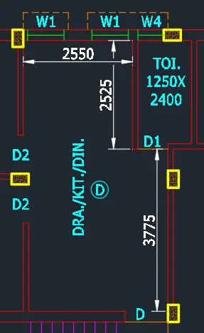
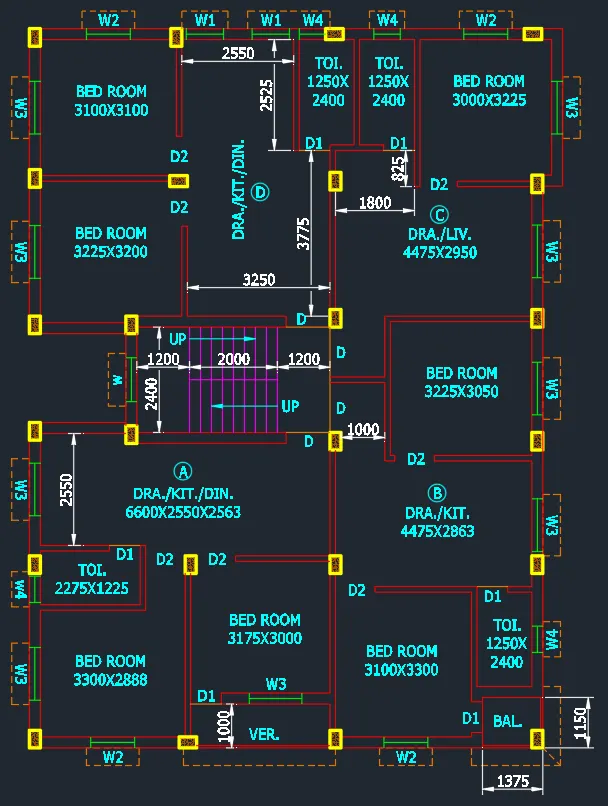
- Add the section marks to finish the sketch.
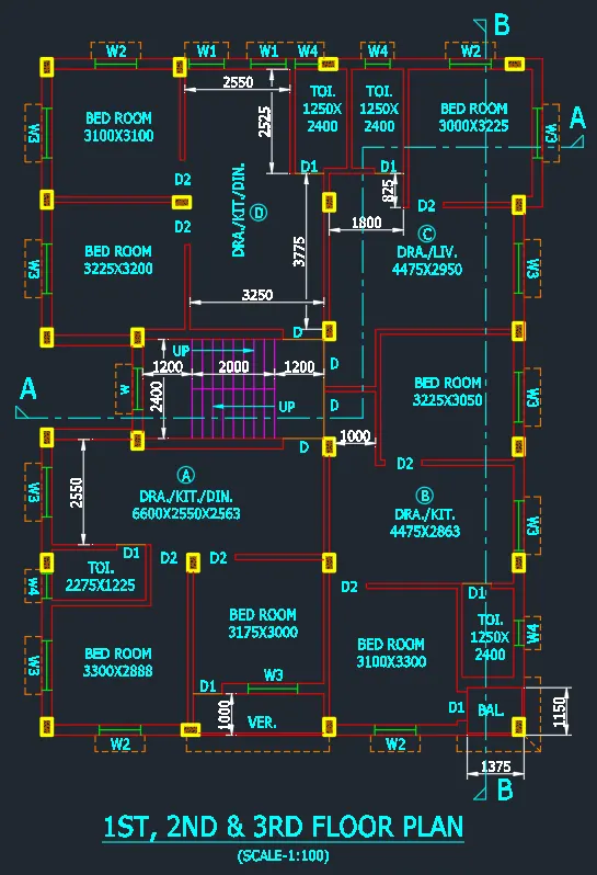
FINAL PRODUCT:
***************
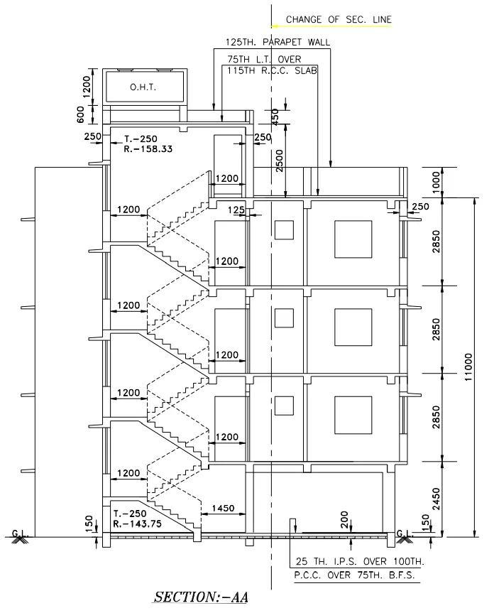
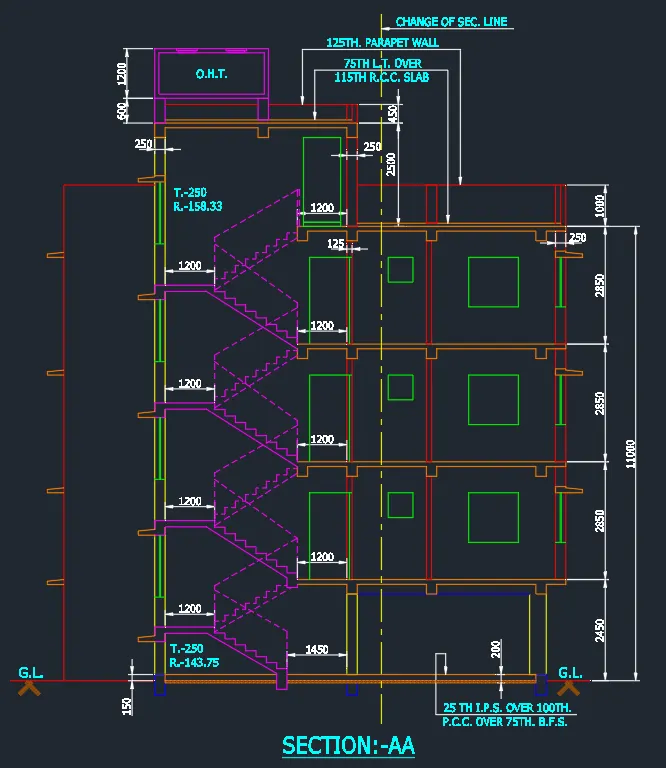
B. SECTION:-AA
PROCEDURE:
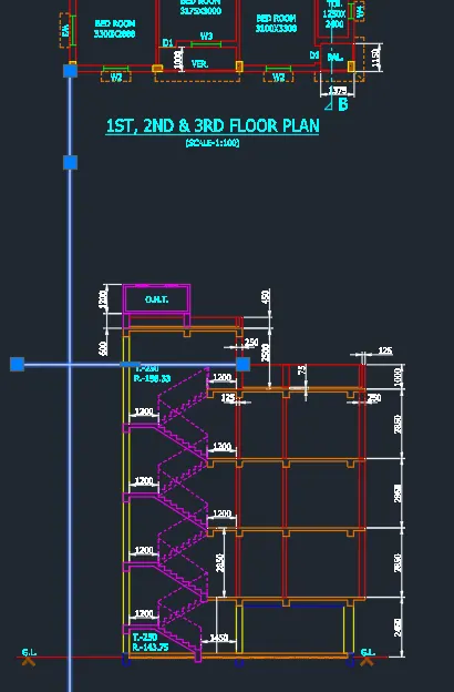
- Project Section AA from plan drawing. Use vertical XLINE or ray tool.
- Then create a horizontal line to act as the base of the elevation. This will be the ground level.
- Beam height is 350mm.
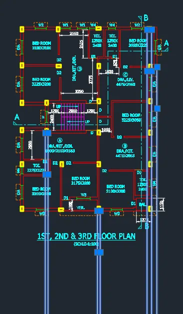
- Use the offset command to project the given elevations. Ignore the stair first to avoid confusion.
- Then sketch the Column according to first projected line.
- Add the dimension for reference.
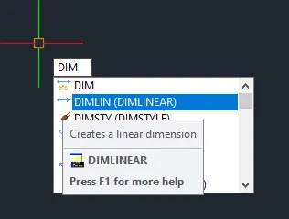
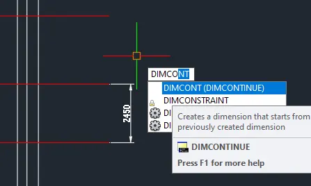
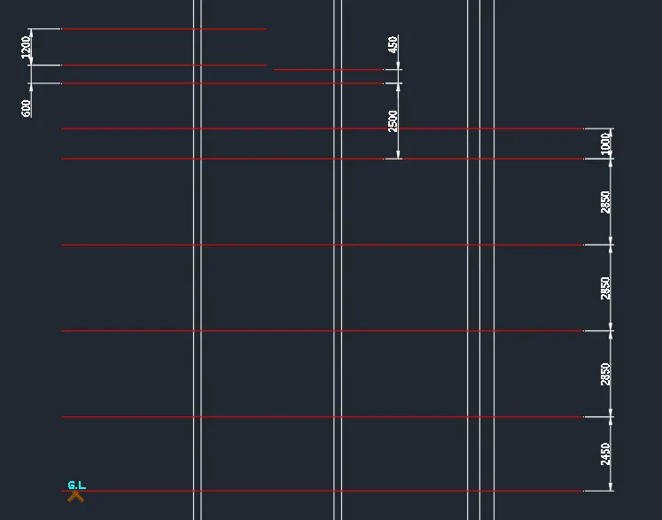
- Project the Ground slab then sketch the columns.
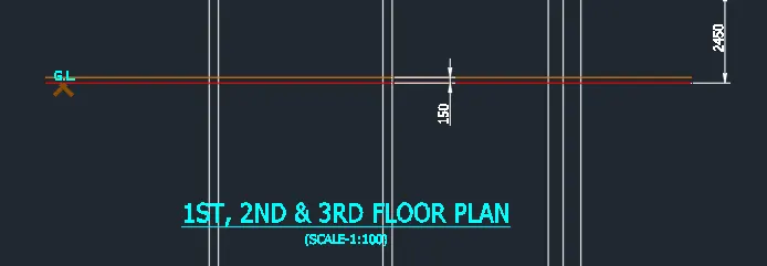
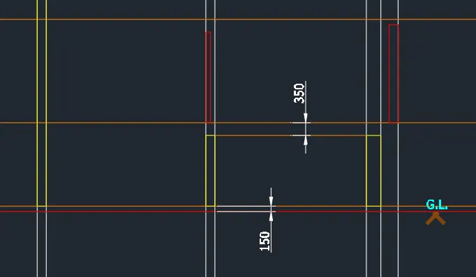
- Trim the excess lines and create the boundaries.
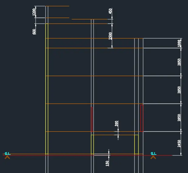
- Complete the sidewall sketch and add beams where required.
- Slab thickness is 115mm. Sketch the at all elevations.
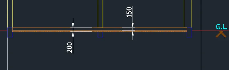
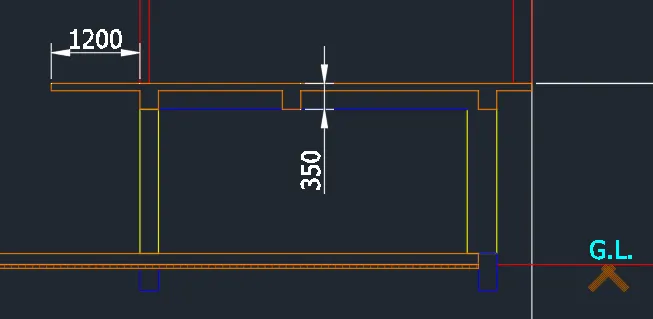
- Continue one by one per elevation.
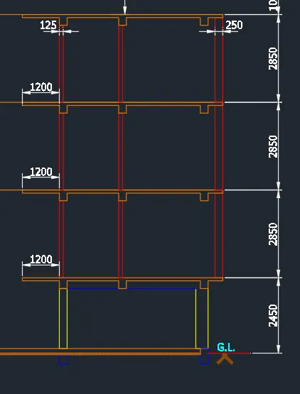
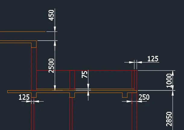
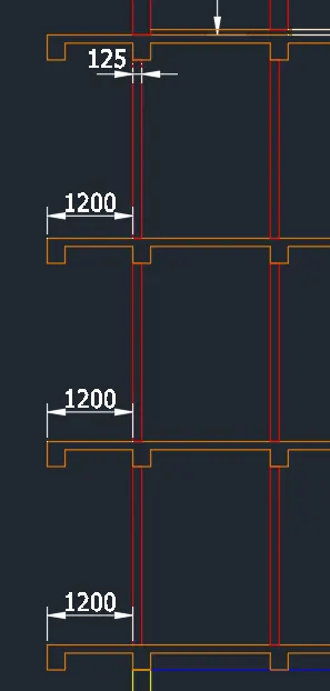
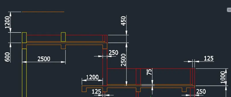
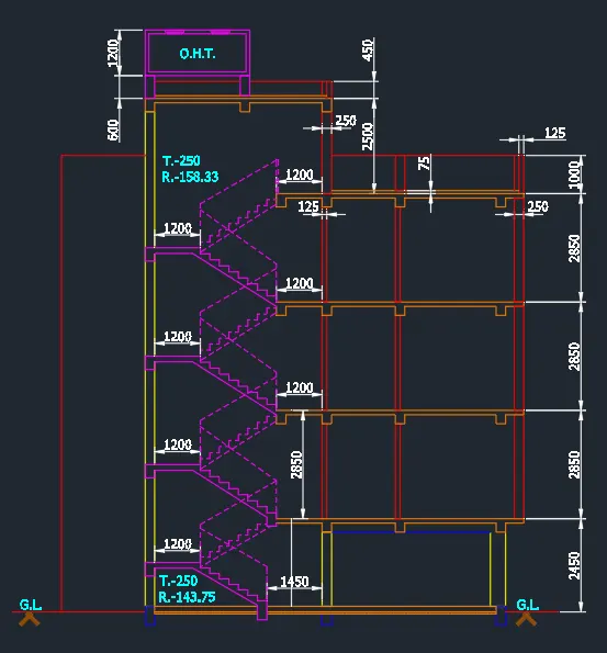
- Proceed the rooftop sketch and draw the tank as shown.
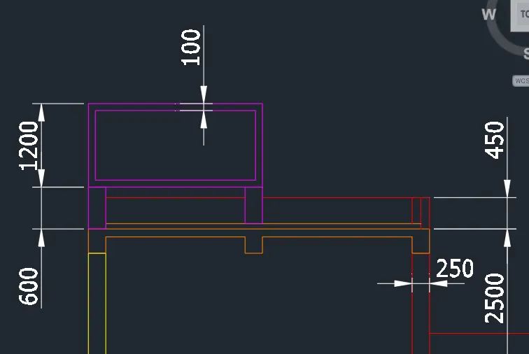
- Adjust the tank dimension and add the top opening.
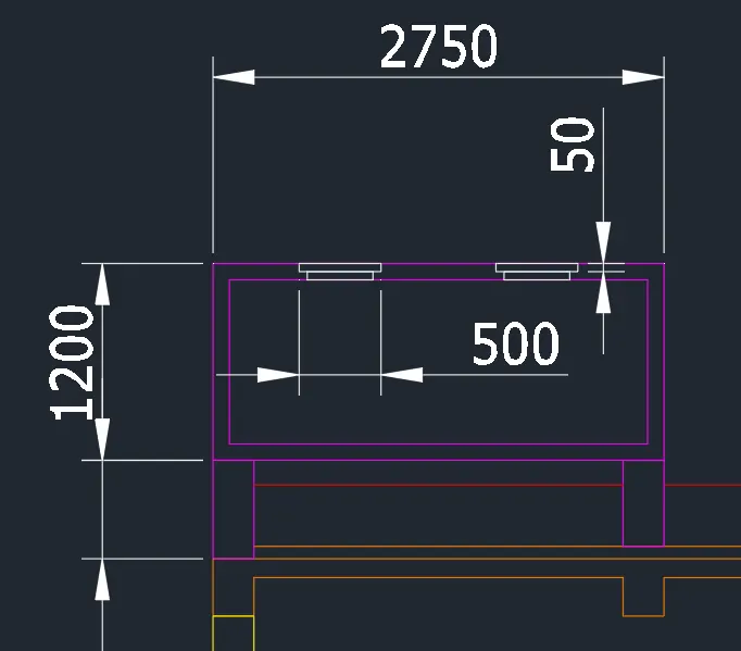
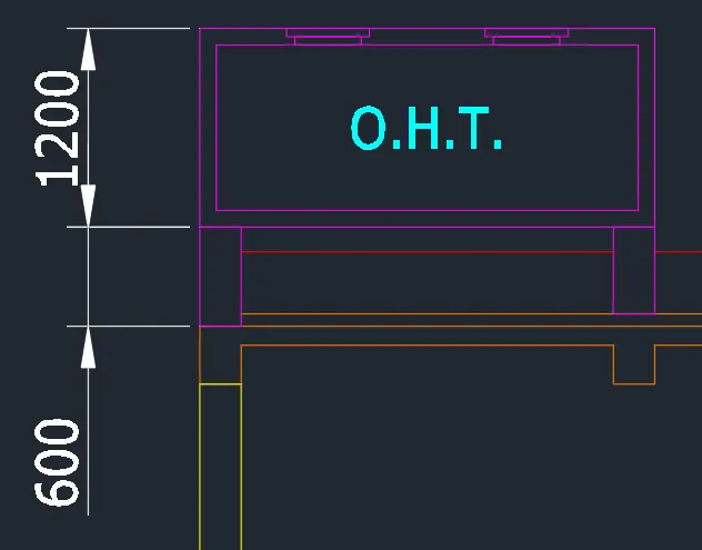
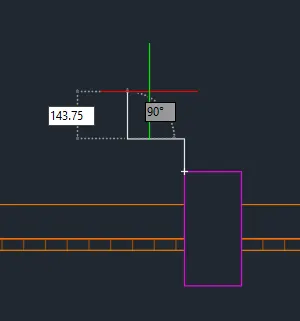
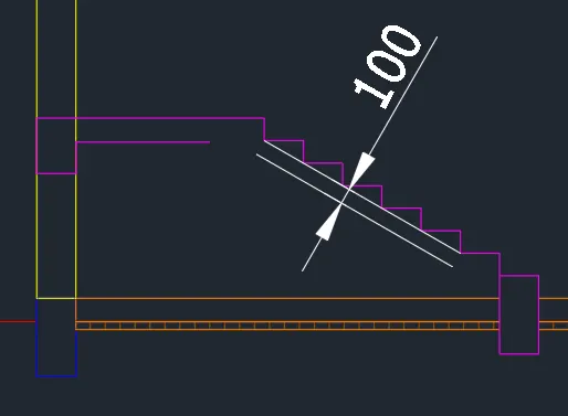
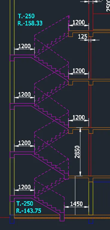
- Proceed with the stairs. Consider the given rise. Change lines to hidden line for those stairs on the other side.
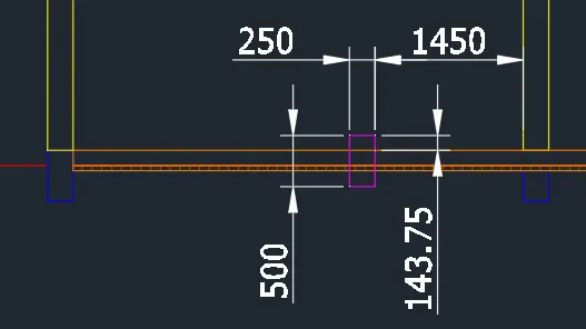
- Trim the unnecessary lines then draw a line representing the rise and thread.
- Take the stair slab as 100mm.
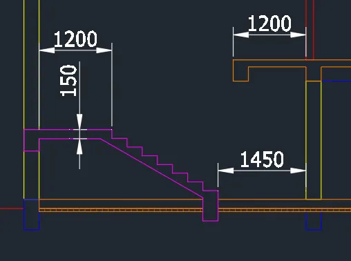
- Continue this steps until you finish the stair.
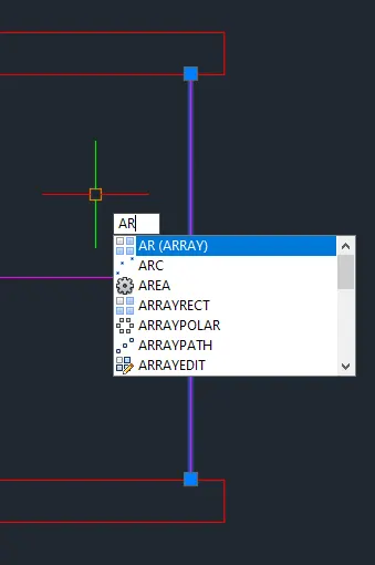
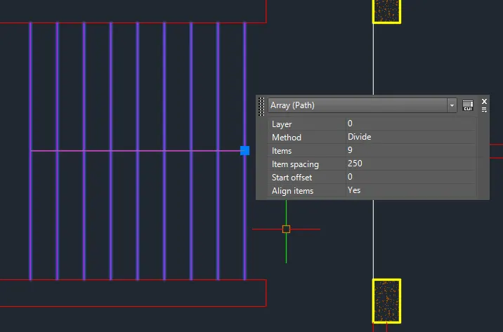
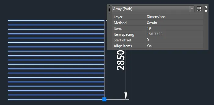
- Use array on a path to get the actual dimension.
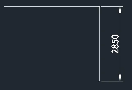
- Draw the canopies at respective places.
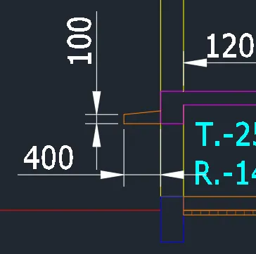

- Add the side windows when adding the canopy.
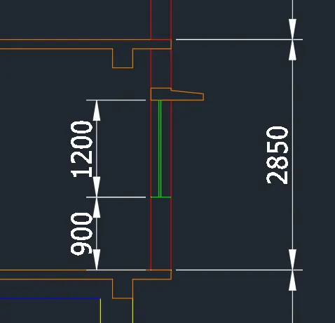
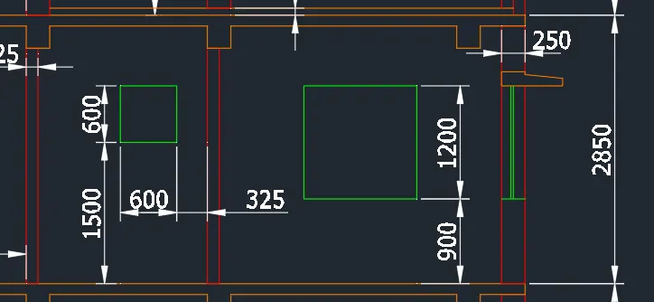
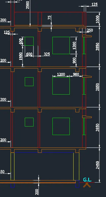
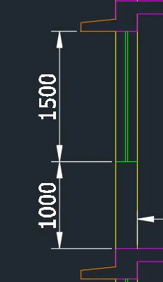
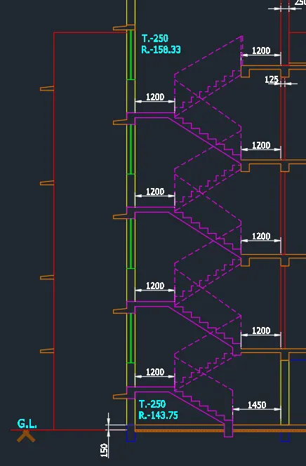
- Add the doors.
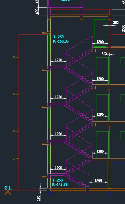
- Add the dimensions. Use dimlinear to provide the dimension.
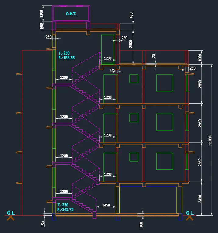
- Add the necessary texts in the sketch using dtext command.
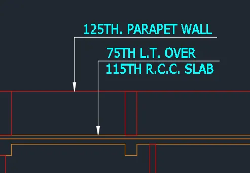
- Add leaders for necessary texts using the leader command or use the Mleader command to add leaders with text.
FINAL PRODUCT:
***************
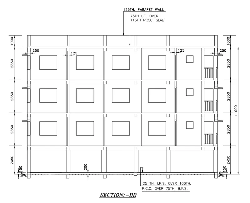
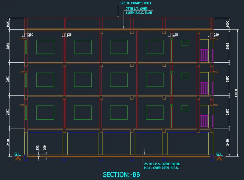
C. SECTION:-BB
PROCEDURE:
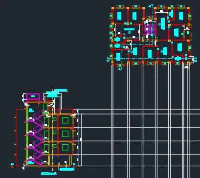
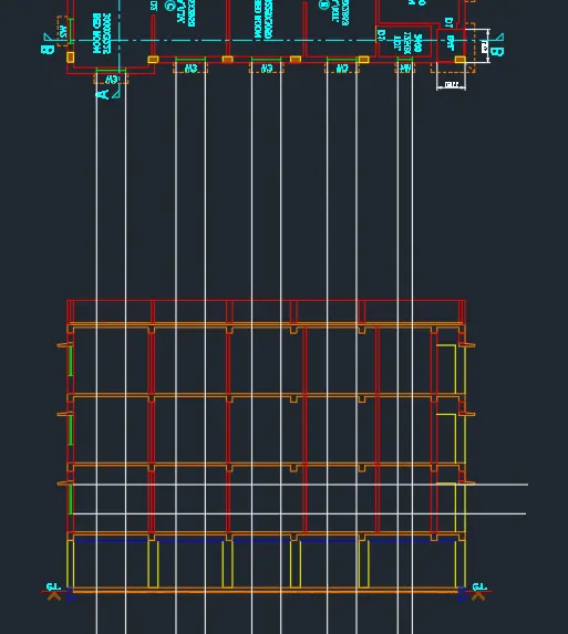
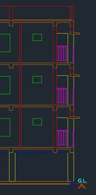
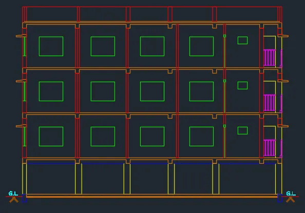
- Sketch this section by copying the plan and rotating it by 90degrees. This will help in projecting the plan.
- Then sketch this one beside section-AA to maintain the elevations.
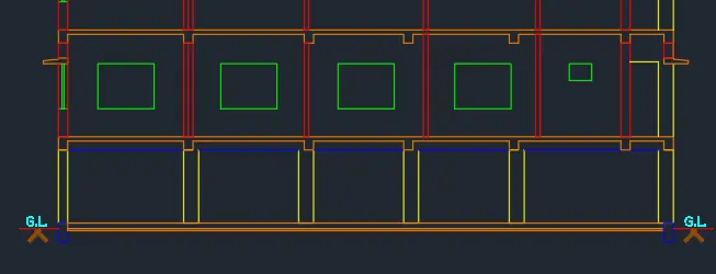
- Start with Columns and walls.
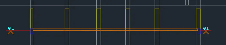
- Sketch it by elevation.

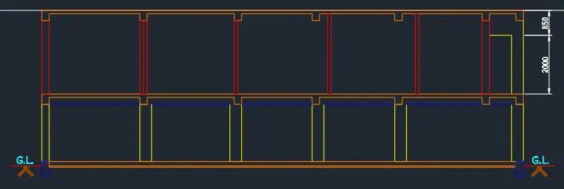
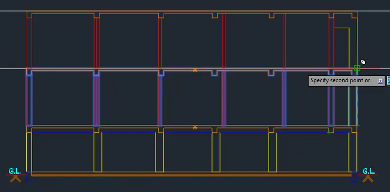
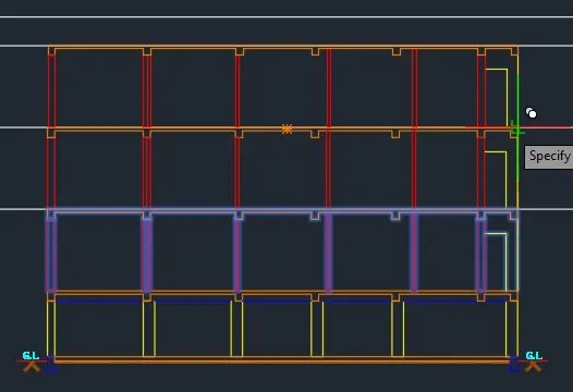
- Follow with the parapet. Sketch the same with AA section.
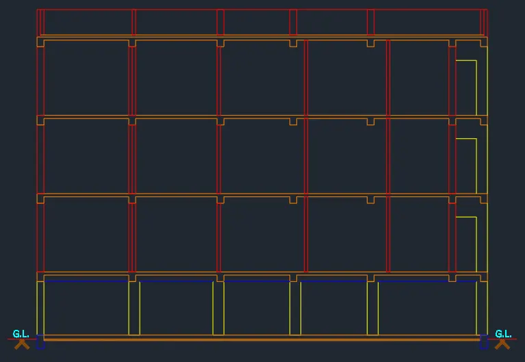
- Create the windows and canopy. You can copy from section AA for faster progress.
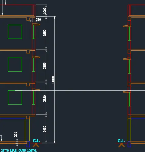
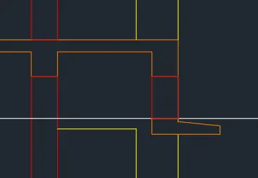
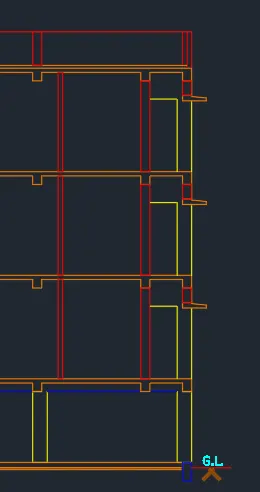
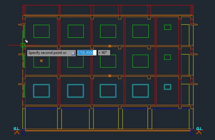
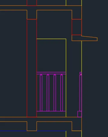
- Create the fence.
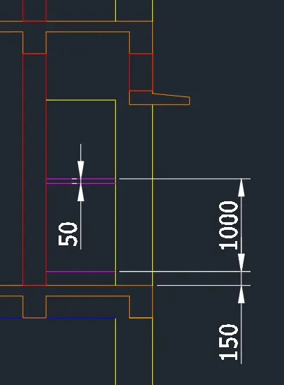
- Add the dimensions. Use dimlinear and dimcontinue.
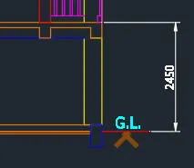
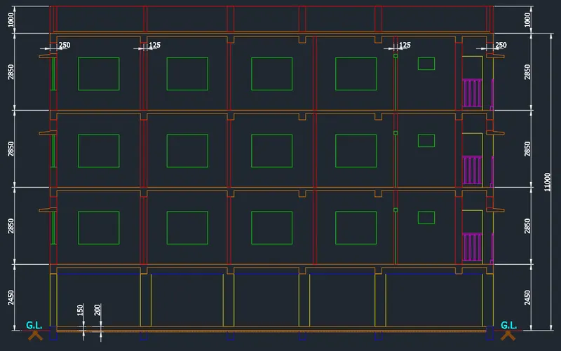
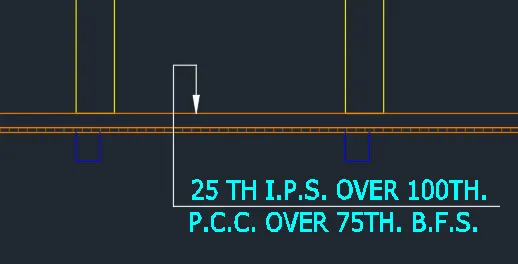
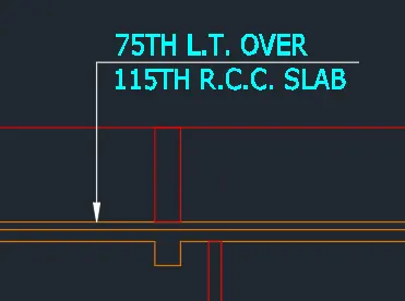
- Add the text and leaders.
FINAL PRODUCT:
********************************************************
3. Conclusion
***************
The AutoCAD software is an essential part of the civil engineering industry. It provides a mean to how the civil engineers portray their design. This sketches help in giving the details needed for the construction of a certain structure. By utilizing all the tools provided by the AutoCAD software, a 2D sketch has been made to illustrate the building. This concludes that the AutoCAD software provides revolutionary technology in the civil engineering industry.