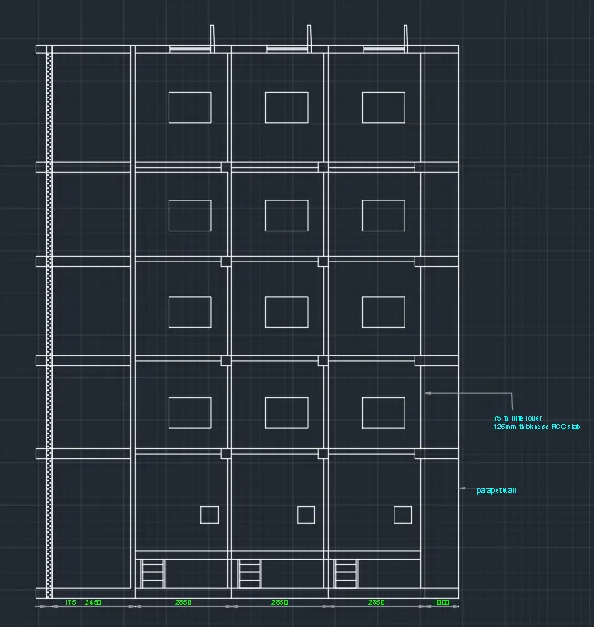
Creating a Layout, Section and Elevation with dimensions using AutoCad
Q1
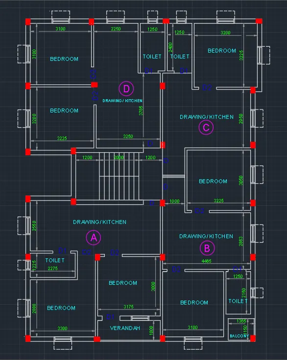
AIM:- To draw the floor plan of the building as per the given dimensions and add text and dimensions as required
step 1:- to draw the exterior walls and partitions
- take an xline command
- specify the first point and draw a horizontal line
- similarly, draw a vertical line
- take the width of exterior walls as 230mm
- take the width of interior walls as 115mm
- then take an offset command and specify the offset distance as required and create rooms and partitions
- then take a trim command and edit the drawing
- then draw the staircase as shown by taking the tread as 250mm
- then add columns of size 230mm x 300mm(assumed)
- then add doors, windows, and other openings wherever required as per the standard sizes
- then take an MTEXT command and add room labels and name the windows and doors as per the sizes
- then add the sunshades on the outer side of the windows and ventilators
Q2
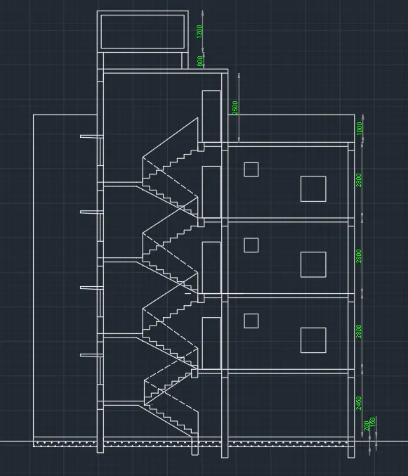
AIM:- to draw the elevation cross-section of the plan and show the details as required
- take a vertical line from the plan following the section details
- then draw a horizontal line
- then take an offset of 150mm to show the details of pcc
- then take an offset of 2450 as the ground floor height
- then take an offset of 125mm from the top to show the thickness of the slab
- then construct a staircase by taking the tread as 250mm and riser as 143.75mm
- show the details of landing (width of the landing is taken as 1200mm)
- show the parapet wall for the staircase(height of the parapet is taken as 900mm)
- then take an offset of 2850 from the top horizontal line to show the height of the first floor
- then show the thickness of the slab as 125mm
- draw the staircase and elevation of the door
- elevation of the window at the sill level as 600mm
- elevation of the ventilator
- then select the details of the first floor and copy the details for the second and third floor
- then show the parapet wall height as 1000mm for the third floor
- and show the details of the headroom for the staircase and overhead tank
- height of the headroom is taken as 2500mm
- show the details of the overhead tank placed at a height of 500mm from the floor level and the depth of the tank is taken as 1200mm
- show the details of windows and sunshades
Q3
AIM:- to draw the elevation of the crosssection BB
- take a line along the section of the plan showing the columns
- then draw a perpendicular line
- take an offset of 2450mm to show the height of the ground floor
- take an offset of 2850mm to show the height of the first, second, and third floor
- then take an offset of 150mm to show the thickness of the RCC slab
- then take an offset of 1000mm to show the height of the parapet wall
- then draw a window at a sill level of 600mm and the height of the window is taken as 1000mm
- then draw a ventilator width a height of 500mm
- then add dimensions and text wherever required