Creating a Layout, Section and Elevation with dimensions using AutoCad
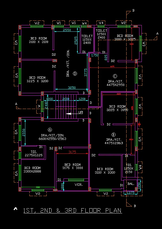
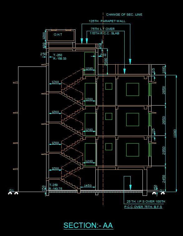
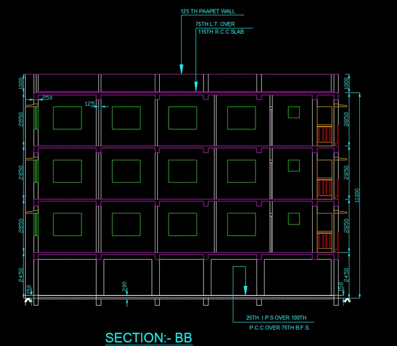
1. Create the Plan and Sections as shown in the Figures. Use proper dimension techniques and dimension styles to document the project. Assume the sizes of the doors and windows as per construction standards. Refer to sections for stair details if required.
AIM:
Create the Plan and Section as shown in the figure.
TOOLS:
IMPORTING PDF FILE
SCALING
XLINE
LINE
OFFSET
TRIM
RECTANGLE
TEXT
DIMENSION
MULTILEADER
HATCH
CIRCLE
DOTTED LINES
LAYER PROPERTIES
BLOCK
INSERT
PROCEDURE:
SKETCHING THE PLAN:
STEP-1:
IMPORTING PDF FILE:
Importing the given PDF file into AutoCAD drawing by using the IMPORT PDF tool.
Invoking the Tool:
RIBBON > INSERT > PDF IMPORT
STEP-2:
SCALING:
Scale the drawing as per the given dimension
Invoking the Tool:
COMMAND: SC >
Select the object and take one base point of the drawing then by the reference of the new length give the required length as given in the drawing.
STEP-3:
Creating the different layers for a better understanding of the drawing.
Invoking the Tool:
RIBBON: HOME > Layer Properties
STEP-4:
XLINE:
Draw the one vertical Xline and one Horizontal Xline at the base.
Invoking the Tool:
COMMAND: XL >
STEP-5:
OFFSET:
Offset the Horizontal X lines and Vertical X lines as per the wall thickness and room dimensions are given in the reference drawing.
The thickness of the External walls is 250mm and the Internal walls are 125mm.
STEP-6:
TRIM:
Trim the extended lines over the rooms and X lines, make the proper plan.
STEP-7:
RECTANGLE:
Created the columns using the rectangle tool. size of the column is 250X400mm
Invoking the Tool:
COMMAND: REC >
STEP-8:
BLOCK:
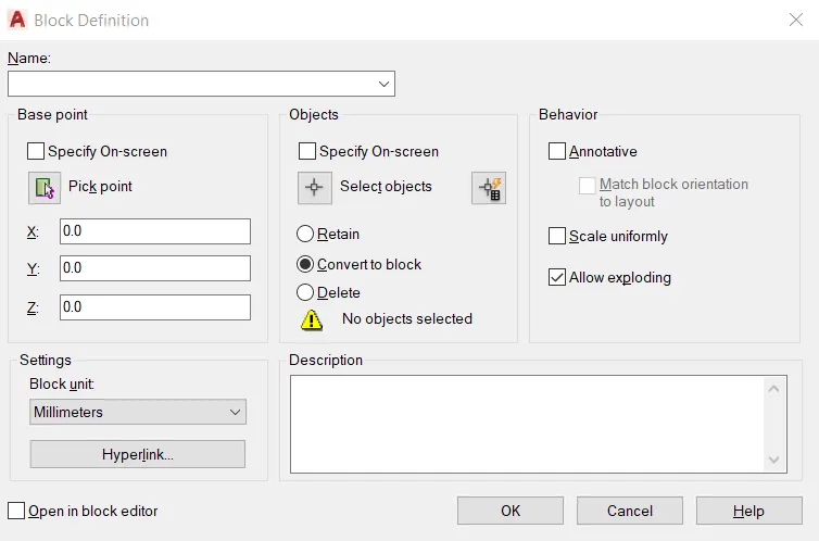
Creating Different blocks like Door, Window.
Invoking the Tool:
COMMAND: B >
Size of the Doors
D = 1000 X 2100
D1 = 750 X 2000
D2 = 900 X 2100
Size of the Windows
W = 1000 X 1000
W1 = 900 X 900
W2 = 1200 X 1200
W3 = 1500 X 1500
W4 = 600 X 600
STEP-9:
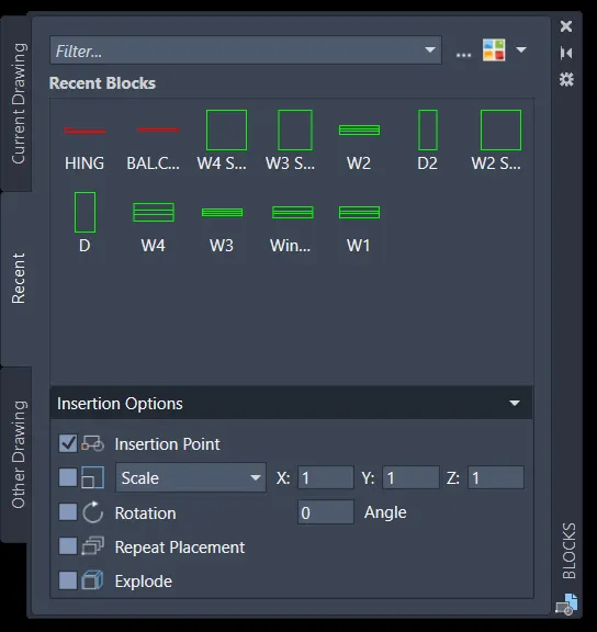
INSERT:
Inserting the created Doors and Window blocks at the positions.
Invoking the Tool:
COMMAND: I >
STEP-10:
MTEXT:
Nameing the rooms using the Mtext tool.
Invoking the Tool
COMMAND: MText >
STEP-11:
DIMENSIONS:
COMMAND: DIMLIN>
Given the dimension as where it required
STEP-12:
DOTTED LINE:
Dotted lines are the projection of Sunshade.
Creating the one new layer with line type dotted line
LINE TYPE SCALE:
COMMAND: LTS>
SKETCHING THE SECTION:- AA:
STEP-1:
XLINE:
Draw the vertical Xline from the plan.
Invoking the Tool:
COMMAND: XL >
STEP-2:
OFFSET:
Offset the Horizontal X lines as per the wall thickness and room dimensions are given in the section-AA drawing.
The thickness of the External walls is 250mm and the Internal walls are 125mm.
STEP-3:
TRIM:
Trim the extended lines over the rooms and X lines.
STEP-4:
Sketching the steps by using the line tool.
landing slab thickness = 120mm
Riser 143.75mm
Tread 250mm
Above first-floor steps sizes are varies
Riser = 158.33mm
Tread = 250mm
STEP-5:
Creating the Blocks of Doors and Windows
STEP-6:
Inserting the created blocks at the respective places.
STEP-7:
Dimensioning and Creating a multileader for defining the thickness of the slab, flooring, B.S.F.
SKETCHING THE SECTION:- BB:
STEP-1:
XLINE:
Draw the Horizontal Xline from the plan.
Invoking the Tool:
COMMAND: XL >
STEP-2:
OFFSET:
Offset the vertical X lines as per the wall thickness and room dimensions are given in the section-BB drawing.
The thickness of the External walls is 250mm and the Internal walls are 125mm. and column size are 250X400mm
STEP-3:
TRIM:
Trim the extended lines over the rooms and X lines.
STEP-5:
Creating the Blocks of Windows
STEP-6:
Inserting the created blocks at the respective places.
STEP-7:
Dimensioning and Creating a multileader for defining the thickness of the slab, flooring, B.S.F.
RESULT: