Creating a Layout, Section and Elevation with dimensions using AutoCad
Aim:
To sketch the Plan and sections of the given building
Introduction:
- Floor plans are scale drawings that show the relationship between rooms, spaces and physical features viewed from above
- Exterior elevation drawings detail the exterior of a home. This provides information regarding where the windows, doors, and exterior trim can be found, as well as illustrations on the wall heights, roof pitches, and ridge heights
- Building sections and details show how the different levels and areas of the plan work in conjunction with each other—while the roof plan provides a bird’s eye view of the home
- This drawing contains standard notes and details that are required to be listed in order to be in compliance with building codes
Procedure:
Open AutoCad
Take a new drawing by QNEW and select decimals and set precision to 0.0
Set the units
Set the LIMITS, that is lower limit as 0.0 and upper limit as 1000,1000
Set the Scale as 1:100
Type Zand then A to zoom all
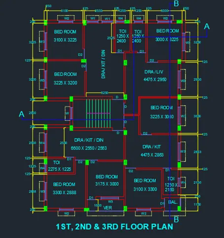
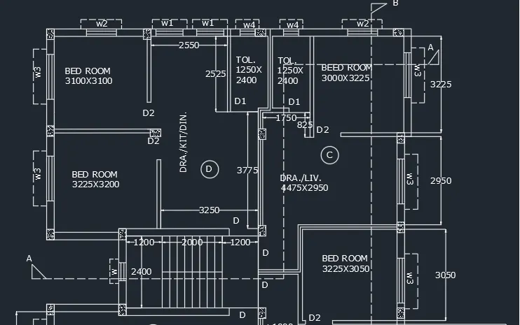
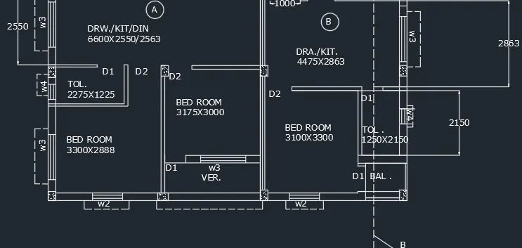
•Sketching PLAN:
Draw constructions lines vertically and horizontally using the command, XL-V and XL-H, and give the thickness of the wall, as outer wall
thickness as 250mm and inner wall thickness as 125mm
Now, using OFFSET command, give the dimension of the Bedroom (3100 3100)
Using OFFSET command, give the inner wall dimension as 125mm
Now OFFSET horizontally 2550,125, 1250 (for toilet), 125, 125, 1250, 3000, 250mm
Now OFFSET vertically, 2950mm from the bedroom of Cand give wall thickness of 125mm, 3250mm and 3200mm. Also give the wall
thickness as 250mm
Divide the rooms horizontally by offsetting 3225mm, 125mm, 3250mm, 125mm, 4475mm and 250mm
Now OFFSET 2400mm vertically and 4400mm horizontally for the staircase.
Using OFFSET command offset 3050mm vertically from drawing of Cand 3225mm horizontally for the bedroom of B and offset the wall thickness too.
Now using OFFSET command offset 3300mm vertically and 3100mm horizontally for the front bedroom.
Fillet the wall of the Bedroom with the left side wall and give wall thickness of 250mm
Now offset 100mm from the outer wall and sketch verandah by offsetting 1000mm and offset 3175mm for the bedroom of A.
Using OFFSET command, offset 2888mm for the front bedroom of A and offset wall thickness of 125mm
Offset 1225mm and 2275mm for the toilet, then offset 2550mm for the drawing/kitchen/dining of A
Fillet all the corners and trim the unwanted lines using TRIM command.
For creating doors and windows, we assume the sizes as:
D=1000*2100mm
D1-700*2100mm
D2-900*210mm
W=600*1200mm
W1=900*1200mm
W2-1000*1200mm
W3=1500*1200mm
W4=500*500mm
Now trim off the size of the doors on the walls, whereever provision for door is given.
Now create the windows of given sizes and place it in respective places.
Using Multiline text, create text box, select the text style and height and type the required text, along with the name of the rooms with sizes of doors and windows
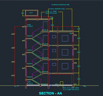
 Sketching Section A-A:
Before sketching the section.
Assume Slab thickness=100mm
Assume Beam=300*350mm
Assume Lintel level from the floor= 2100mm
Assume Lintel thickness=150mm
Assume Staircase waist slab thickness and landing slab thickness=100mm
Assume Height of newel post=1000mm
Now extend the wall thickness wherever the section cuts the plan and draw a horizontal line to show the ground level.
Now draw a 150mm thickness from the ground level by offsetting 150mm from ground level
Using OFFSET command, offset a distance of 2450mm from the ground level for the ground floor height.
Now offset a 100mm from the top level for slab thickness.
Draw the beams of 300*350mm wherever the walls are there and colums of 400*300mm width.
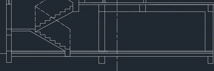
•Sketching Stairs:
Draw a beam of 300 mm width and 270mm depth down the ground level.
Draw a vertical line of 143.75mm as riser, except on the top floor, at a distance of 1450mm from the 300mm
Draw a horizontal line of 250mm
Similarily draw 8 steps, draw the landing from the 8th one and offset a thickness of 100mm downwards.
Now draw an inclined line joining the riser end of the flight, offset 100mm from that line and join it with thelanding slab.
Now Mirror the steps to the opposite side meeting the next floor, given dotted lines as it is invisble.
Now draw a beam of 300*250mm as landing beam.
Give the height of newel post as 1000mm on both the start and end of flight, connect it with inclined line
For the first floor, offset a height of 2850mm, also provide slab thickness of 100mm and beam of 300*350mm
Extend the projected walls of 125mm and 250mm.
Now extend the doors and windows from the plan to get its width, then a height of 1200mm for window and 50mm for ventilator is provided.
Now sketch the lintel slab of 150mm and projection of shade of 400mm is made
Section of the window on one end of the wall and the stair side is shown, as it is cut through by the section line.
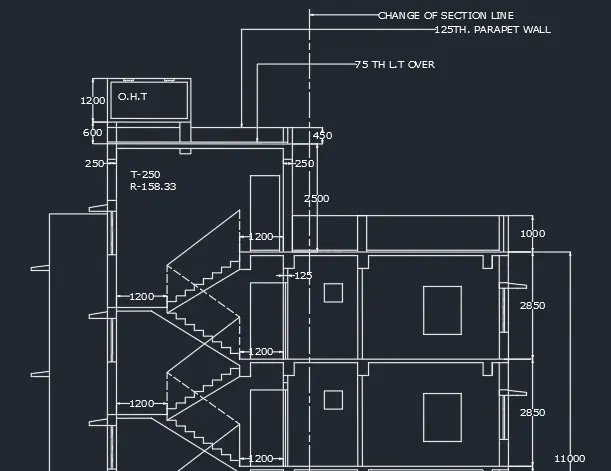
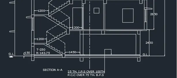
Similarily, copy the same in the respective floors, upto the third floor.
On top of the parapet, give height of 1000mm and 2500mm for the top room.
Now sketch the door of 900*2100mm and wall thickness of 250mm on both sides.
Draw a parapet height of 450mm, for overhead water tank
Extend the wall thickness and the beam
Draw a line of 1200mm as height of tank and 2300mm as width of tank
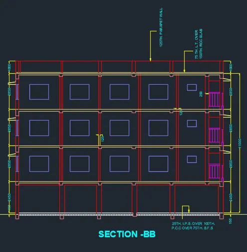
• Sketching Section B-B:
Project the walls and columns from the plan using LINE command.
Mark a vertical line showing the ground level, now using OFFSET command, offset of 150mm for PCC and 200mm from the ground level is made.
Now, project the windows and ventilators and give the height 2100mm
Now offset slab of 100mm thickness and draw the beams
The sections of windows wherever the section line cuts the window is also shown. 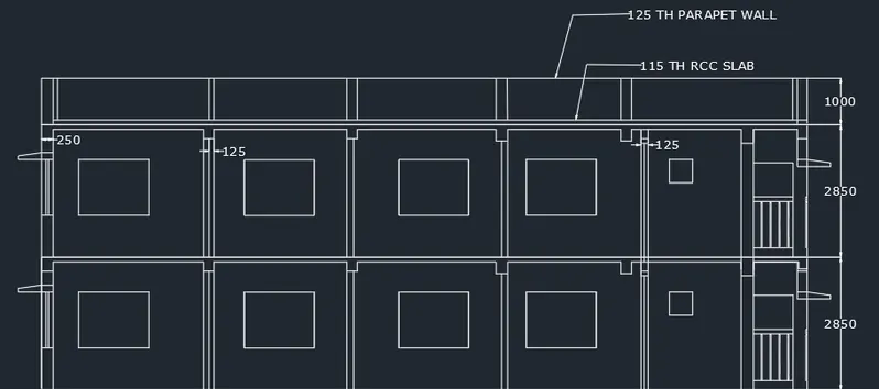
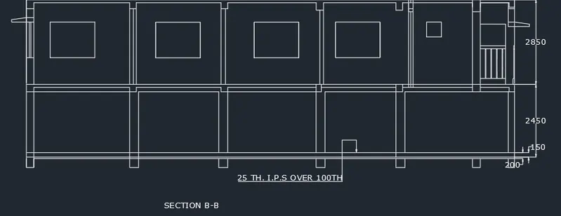
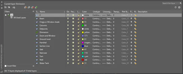
Now layers for external walls, internal walls, windows, doors, text, dimension, stairs,slab, columns and beams are done
•Creation and placing the drawing elements in layers:
Layers are created by using the command "LA" create the layers and give the properties of the layers like colour,line weight, etc.
Create the layers for the walls ,text,dimensions, etc.
Place all the elements in the respective layers.
OUTPUT: