Creating a Layout, Section and Elevation with dimensions using AutoCad
CHALLENGE-7
PREPARED BY- MEGHA GUPTA
Creating a Layout, Section and Elevation with dimensions using AutoCAD.
Aim: Aim of the challenge is to create layout section and elevation with dimensions using AutoCAD.
Introduction: In this project floor plan, section and elevation of a building has been created using various tools available in AutoCAD.
To create the various drawings line, rectangle, dimensions command has been used and annotation command was used to write the text. Hatch command is used for showing the concrete. Different layers have been used for creating the drawings.
Procedure followed for creating the drawing has been discussed below in detail.
- Create the plan and sections as shown in the Figures. Use proper dimension techniques and dimension styles to document the project. Assume the sizes of the doors and windows as per construction standards. Refer to sections for stair details if required.
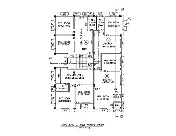
Fig. 1: Floor Plan
Procedure followed for drawing of floor plan details:
- Select the current drawing units as decimal.
- Select line command from the toolbar to create the walls for the plan referring to Fig. 1.
- Wall layer has been used to create walls of the building
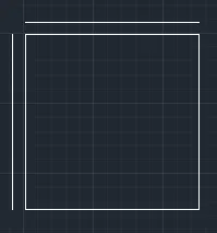
Fig. 2
- Using offset command thickness of the wall was created in the plan. For exterior walls 250mm thickness was used, whereas, for the interior walls 115mm or 125mm thickness was used.

Fig. 3
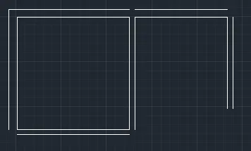
Fig. 4
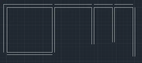
Fig. 5
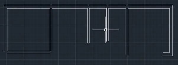
Fig. 6
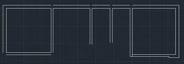
Fig. 7
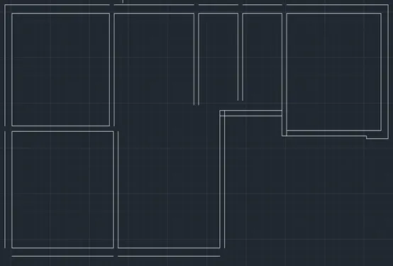
Fig. 8
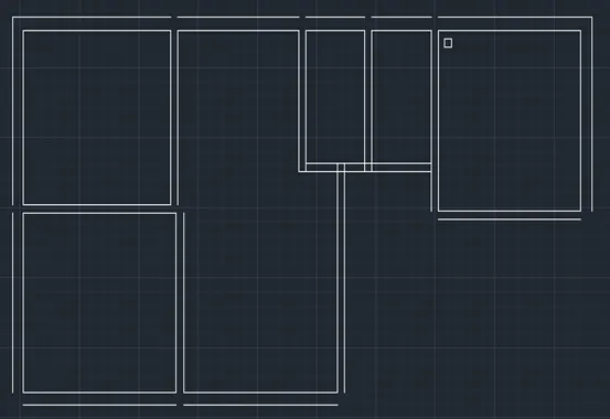
Fig. 9
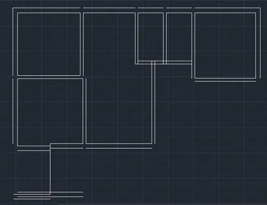
Fig. 10
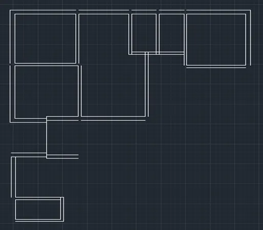
Fig. 11
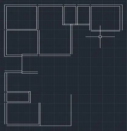
Fig. 12
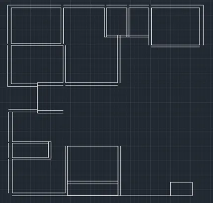
Fig. 13
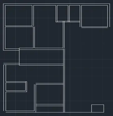
Fig. 14
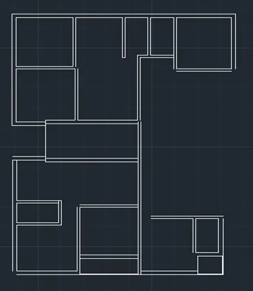
Fig. 15
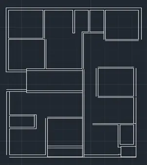
Fig. 16
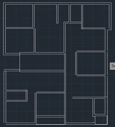
Fig. 17
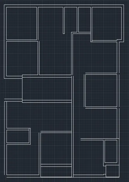
Fig. 18
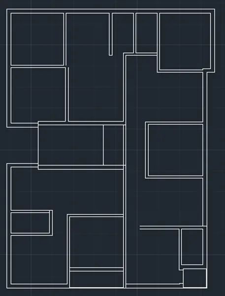
Fig. 19
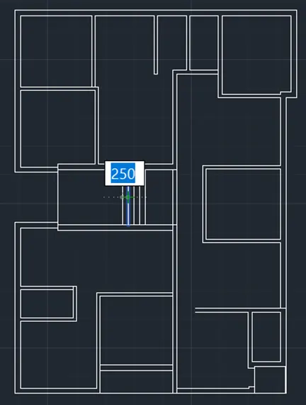
Fig. 20
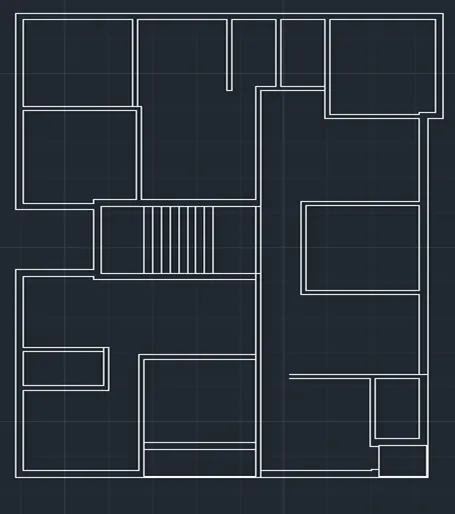
Fig. 21
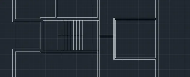
Fig. 22
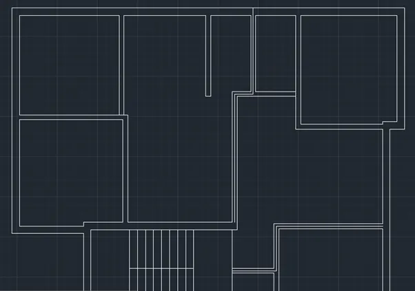
Fig. 23
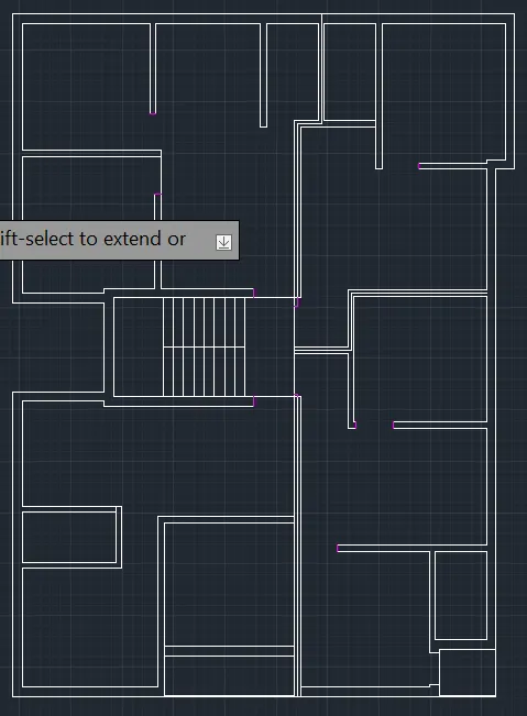
Fig. 24
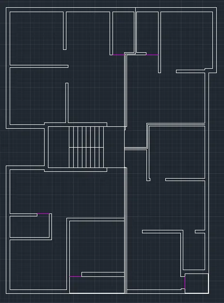
Fig. 25
- Doors and windows were created in “door” layer. Different colour was selected for this layer.
- Turning on the door layer different door and windows were created in the plan using line command referring to Fig. 1.
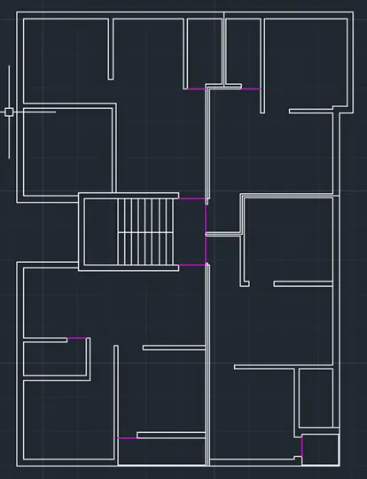
Fig. 26
- Turning on the zero layer and selecting different colour in the bylayer. The columns were created in the plan.
- Hatch command was used from the toolbar to show concrete in the column.
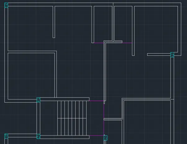
Fig. 27
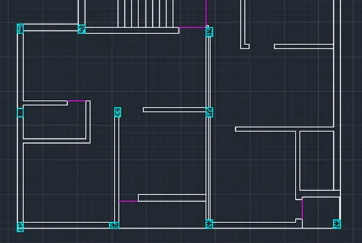
Fig. 28
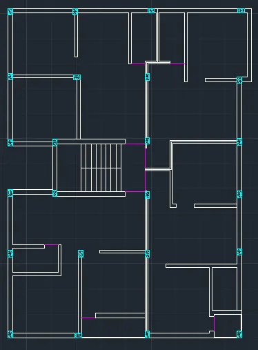
Fig. 29
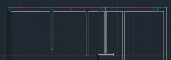
Fig. 30
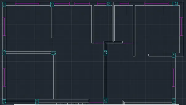
Fig. 31
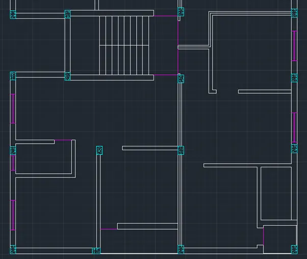
Fig. 32
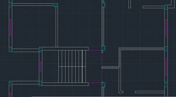
Fig. 33
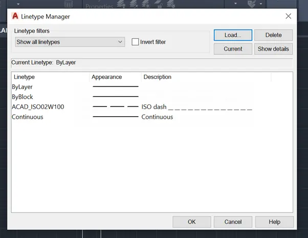
Fig. 34
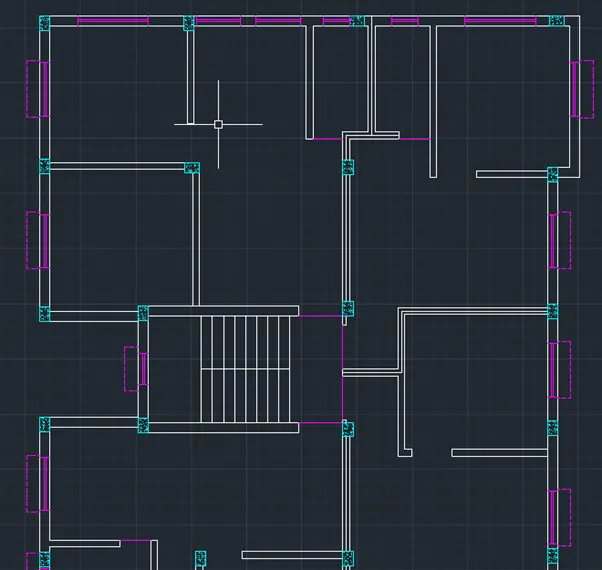
Fig. 35
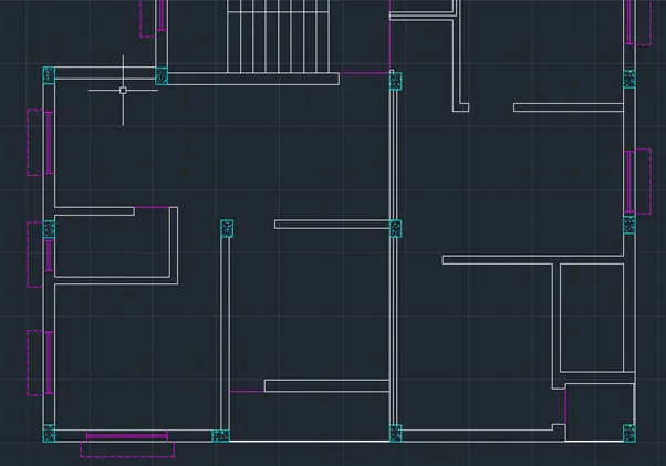
Fig. 36
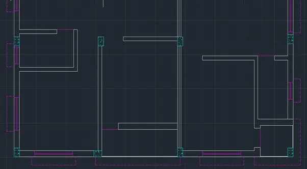
Fig. 37
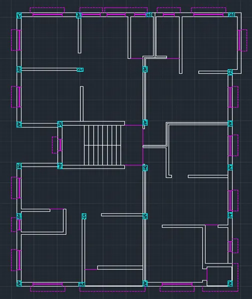
Fig. 38
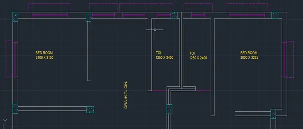
Fig. 39
- Turning on the annotation layer various, room name, room sizes, window names, door names were written in the plan
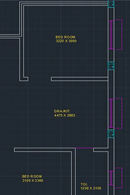
Fig. 40
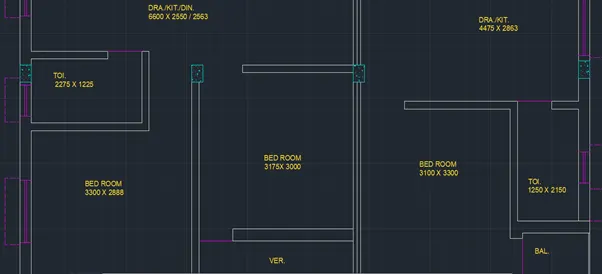
Fig. 41
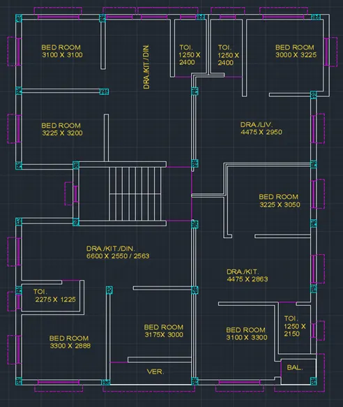
Fig. 42
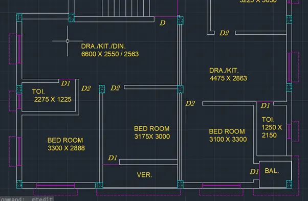
Fig. 43
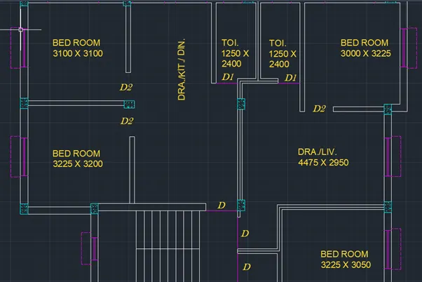
Fig. 44
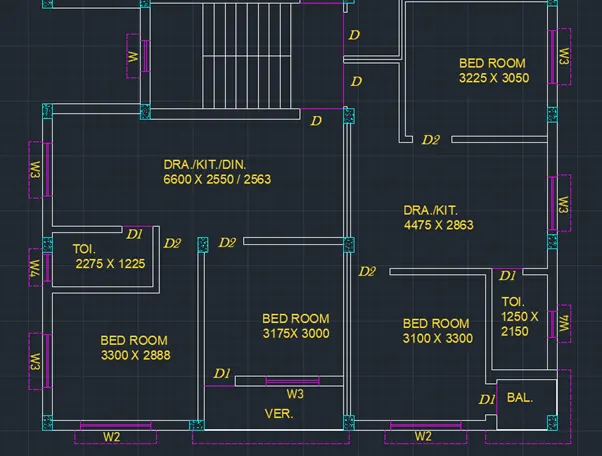
Fig. 45
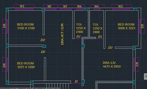
Fig. 46
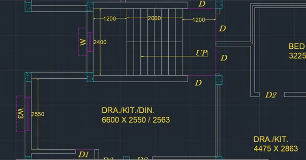
Fig. 47
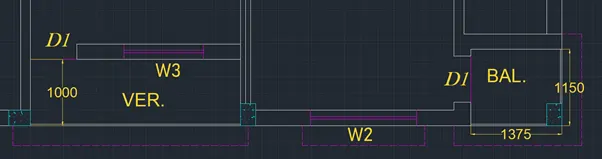
Fig. 48
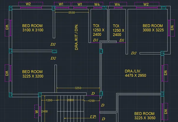
Fig. 49
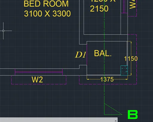
Fig. 50
- From the bylayer dotted dashed line was selected to show the position of cut section in the plan.
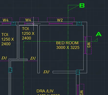
Fig. 51
- Dimensions were given using dimension command from annotation toolbar in the annotation layer.
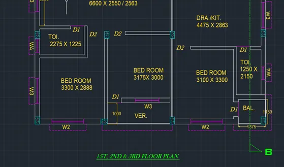
Fig. 52
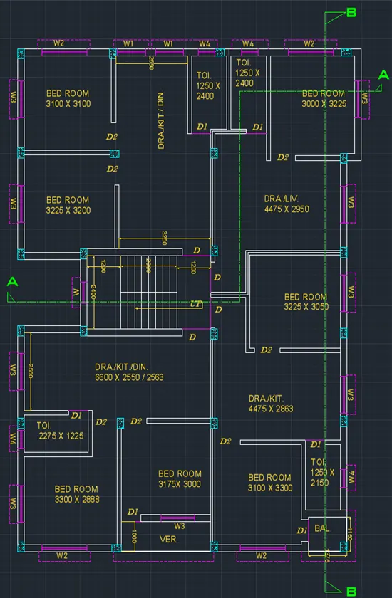
Fig. 53
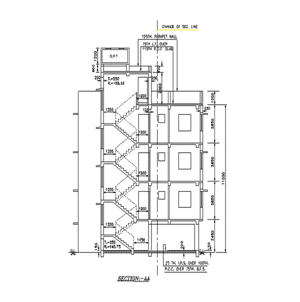
Fig. 54: Section AA
Procedure followed for drawing of Section AA:
- Select line command from the toolbar projections were taken from the floor plan drawn for all the walls coming on the section AA.
- Trim command was used to remove the unwanted portion of the lines.
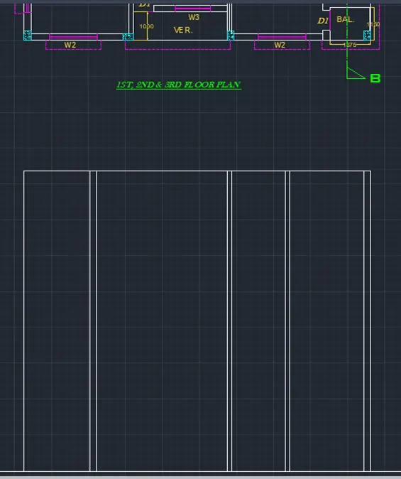
Fig. 55
- Line command was used to draw the base for the section.
- Wall layer has been used to create walls of the building.
- Offset command was to create the lines at some required distance.
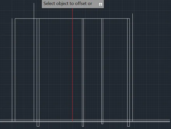
Fig. 56
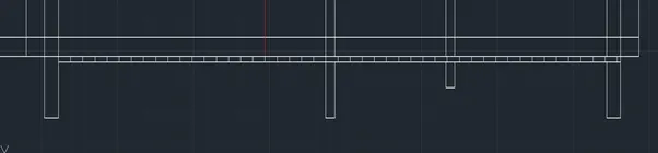
Fig. 57
- Using line command from the toolbar steps were created in the staircase. For the ground floor tread was kept as 250mm whereas the riser was 143.75mm.
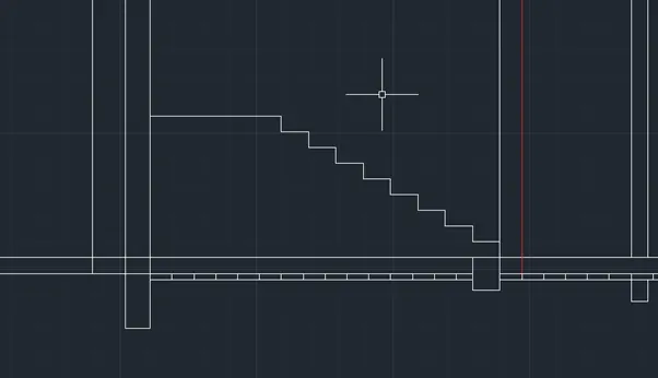
Fig. 58
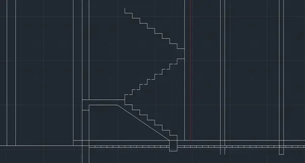
Fig. 59
- Using line command from the toolbar steps were created in the staircase. For the first-floor tread was kept as 250mm whereas the riser was 158.33mm.
- Referring to Fig. 54, draw the column and walls for the section.
- Windows and doors were drawn in the door layer.
- Chajjah were also drawn in the door layer.
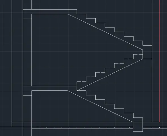
Fig. 60
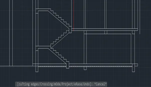
Fig. 61
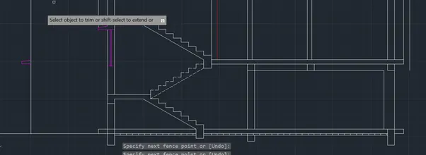
Fig. 62
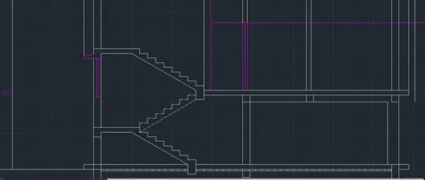
Fig. 63
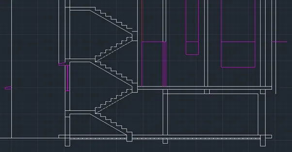
Fig. 64
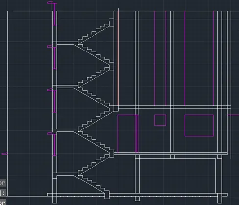
Fig. 65
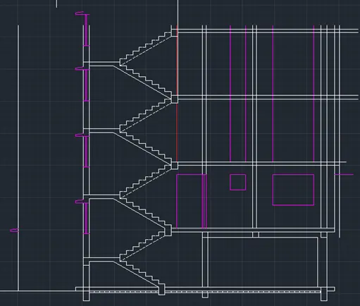
Fig. 66
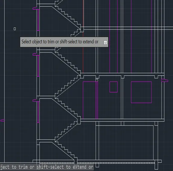
Fig. 67
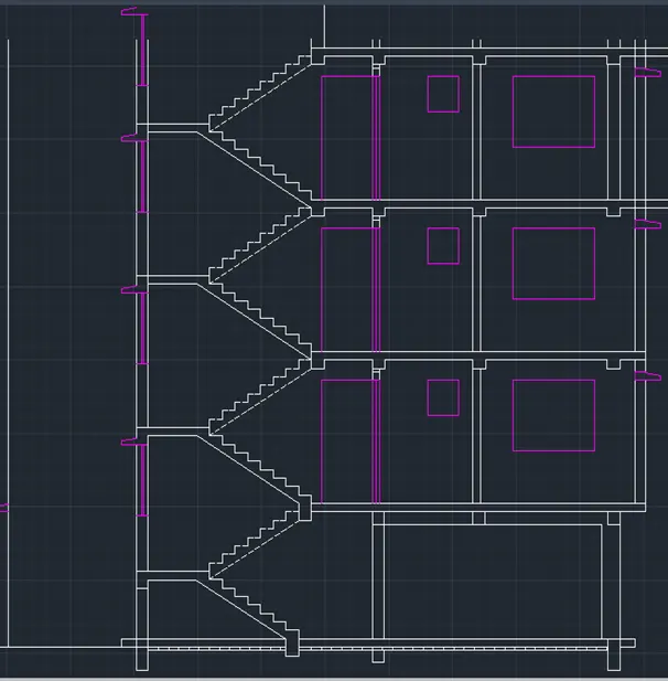
Fig. 68
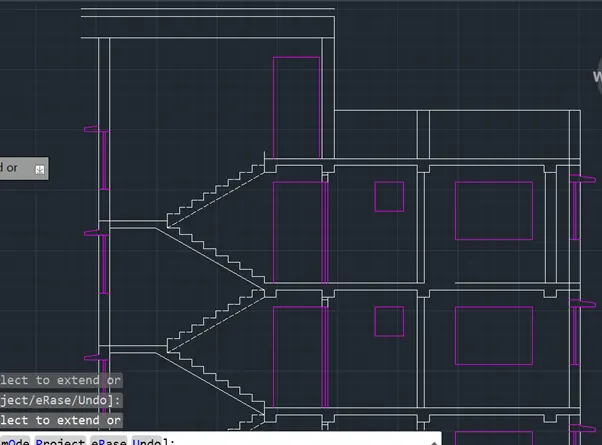
Fig. 69
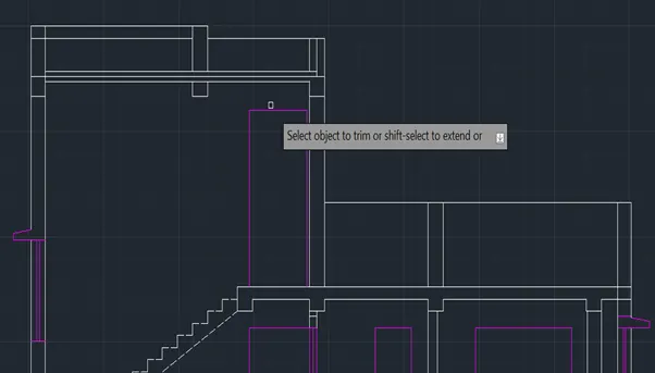
Fig. 70
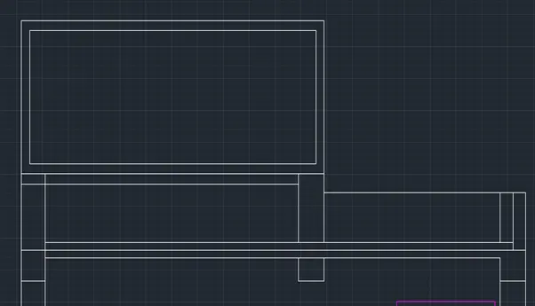
Fig. 71
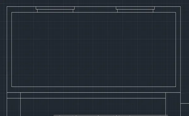
Fig. 72
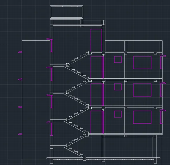
Fig. 73
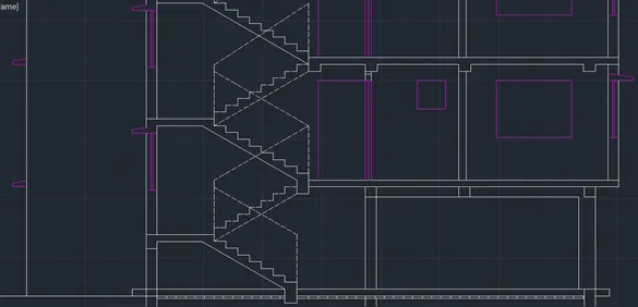
Fig. 74
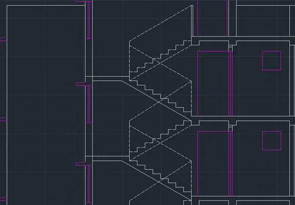
Fig. 75
- Dimension were shown using dimensions command from the toolbar.
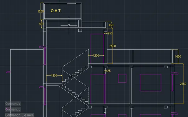
Fig. 76
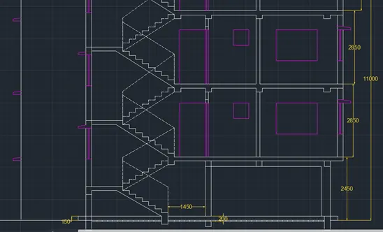
Fig. 77
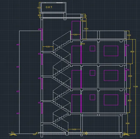
Fig. 78
- Leader command was used to specify the leader. Leader was added in the annotation layer.
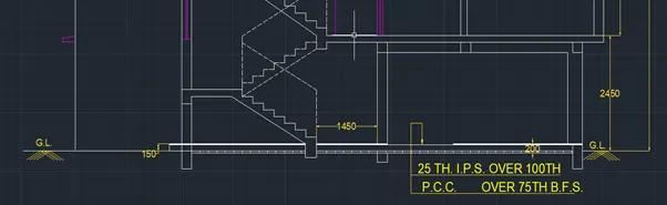
Fig. 79
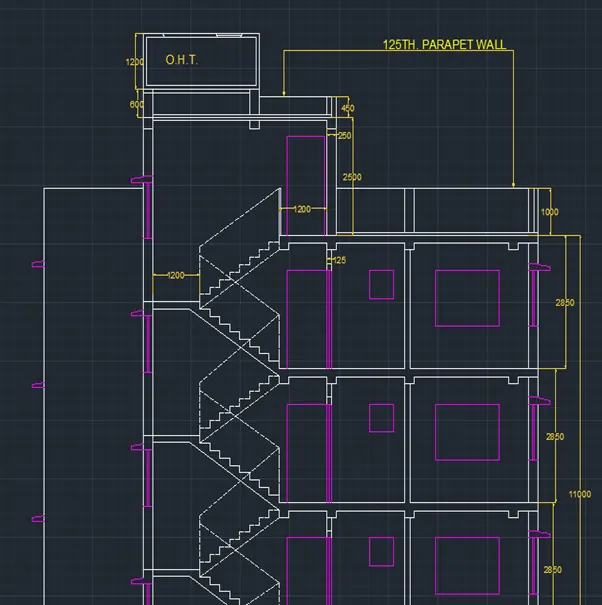
Fig. 80
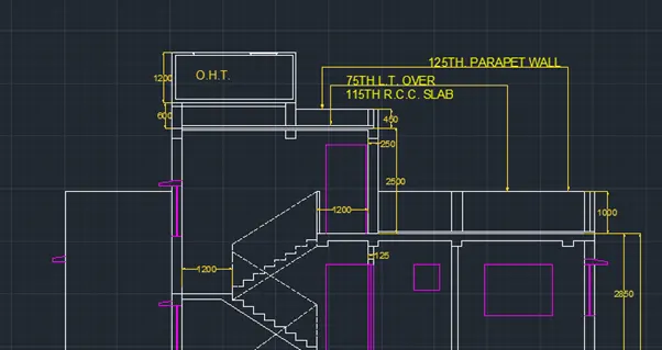
Fig. 81
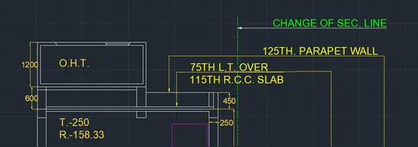
Fig. 82
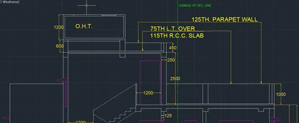
Fig. 83
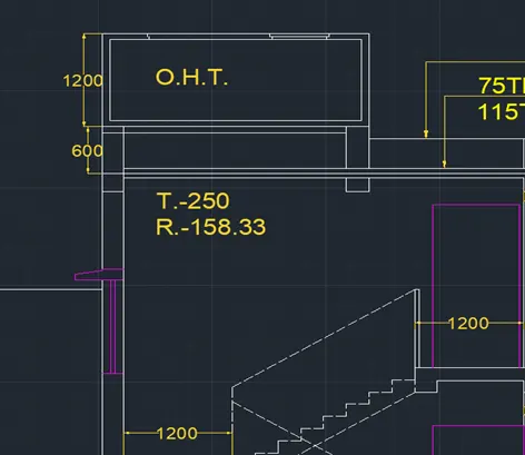
Fig. 84
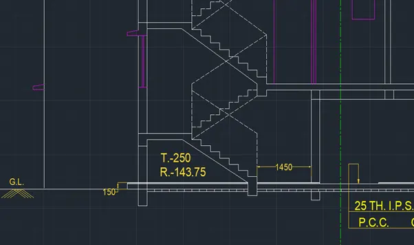
Fig. 85
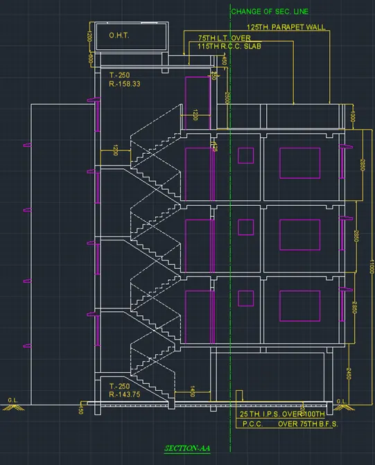
Fig. 86
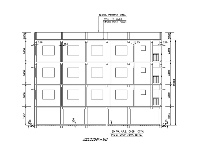
Fig. 87: Section BB
Procedure followed for drawing of Section BB:
- Select line command from the toolbar projections were taken from the floor plan drawn for all the walls, windows coming on the section BB.
- Trim command was used to remove the unwanted portion of the lines.
- Also, Take the projection from section AA drawn in order to get the heights for different floors.
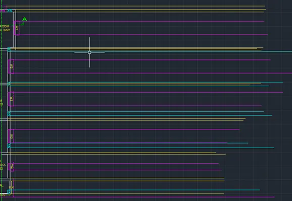
Fig. 88

Fig. 89
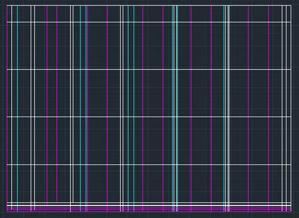
Fig. 90
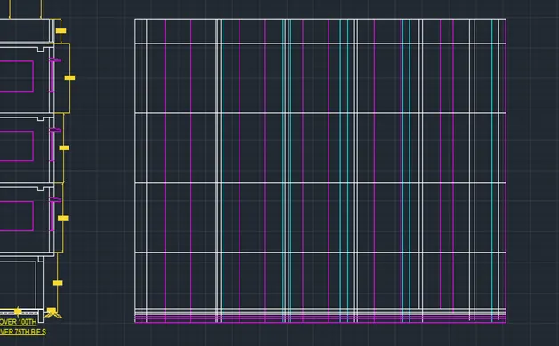
Fig. 91
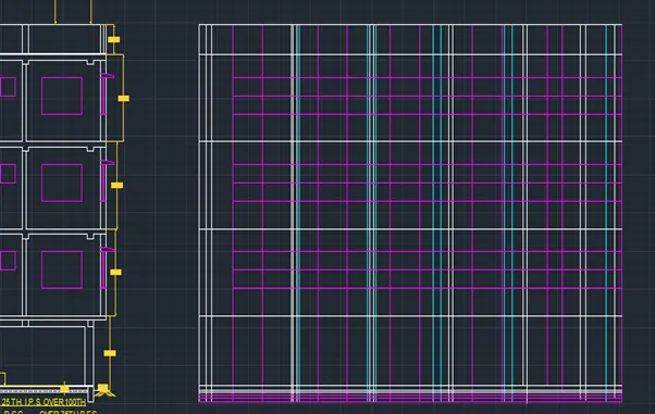
Fig. 92
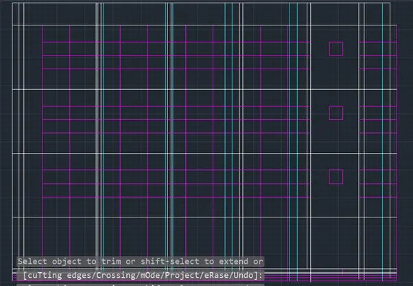
Fig. 93
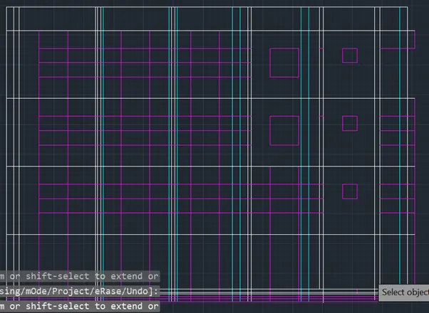
Fig. 94
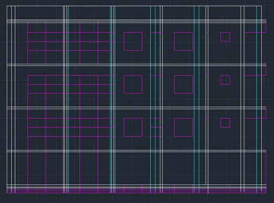
Fig. 95
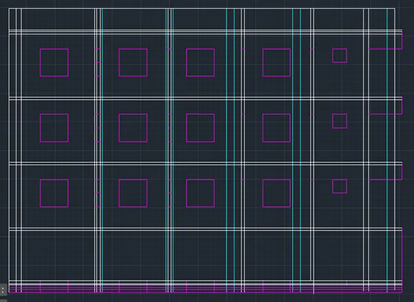
Fig. 96
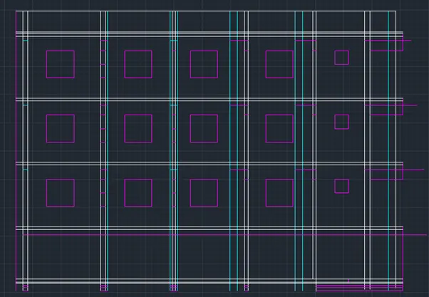
Fig. 97
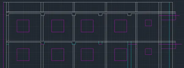
Fig. 98
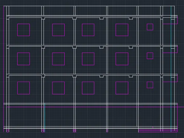
Fig. 99
- Trim command was used to remove unwanted part of the line.
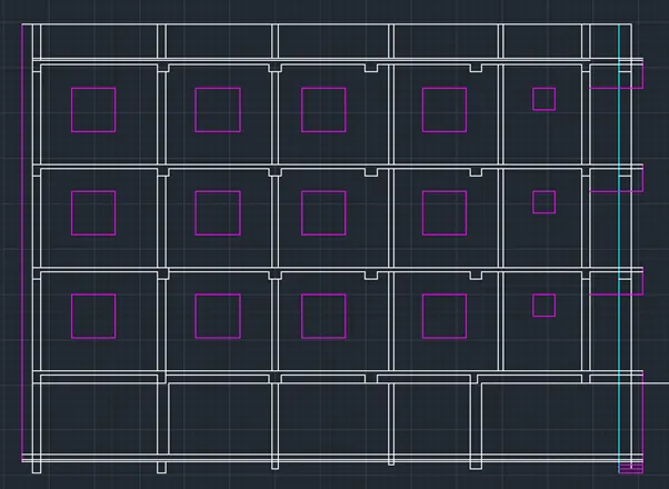
Fig. 100
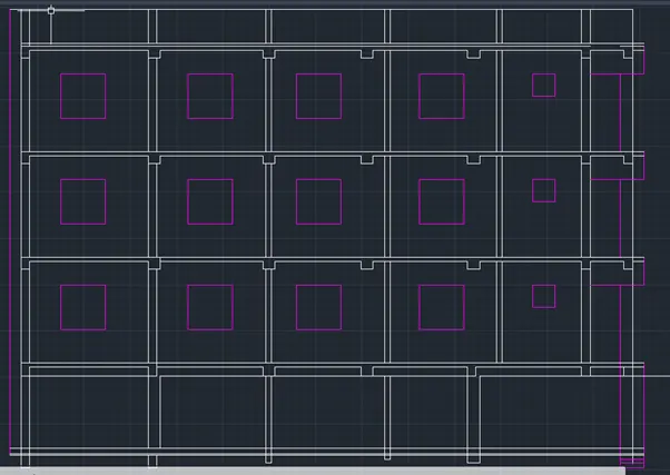
Fig. 101
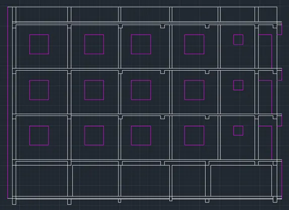
Fig. 102
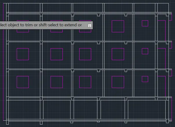
Fig. 103
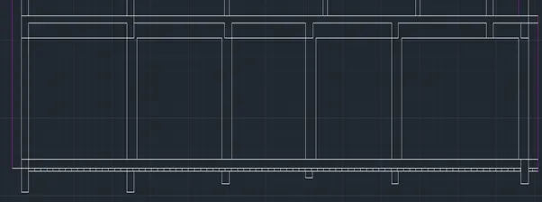
Fig. 104
- Using line command, the railing for the balcony was created and then copied and pasted for different levels using copy command.
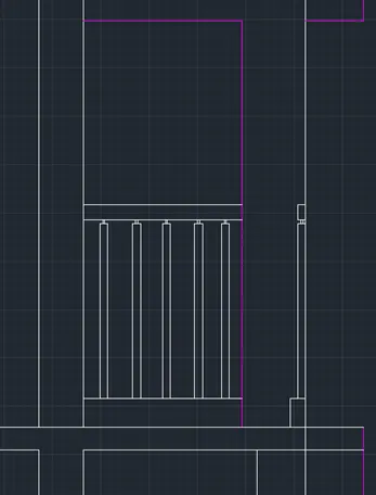
Fig. 105
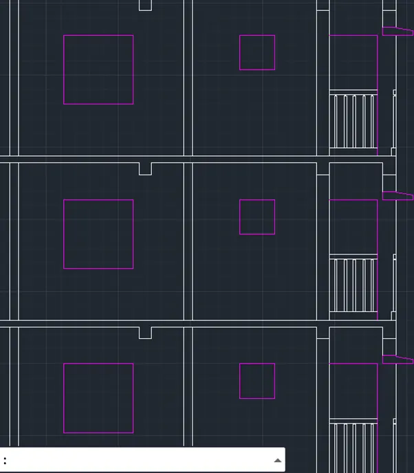
Fig. 106
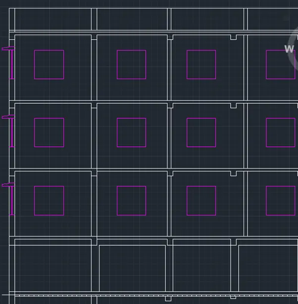
Fig. 107
- Use dimensions to specify the dimensions in the section.
- Leader command was used to specify the leader as per requirement to show the thickness of slabs referring to Fig. 88.
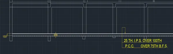
Fig. 108
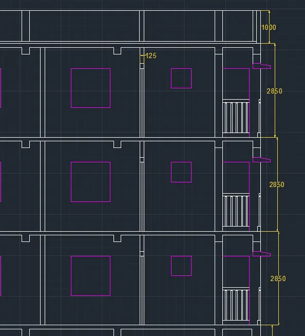
Fig. 109
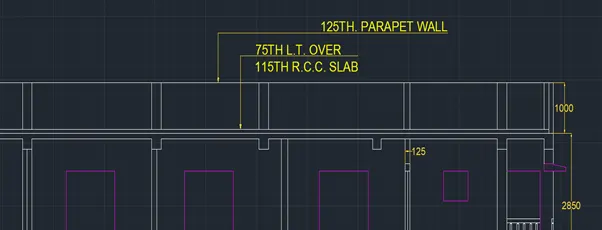
Fig. 110
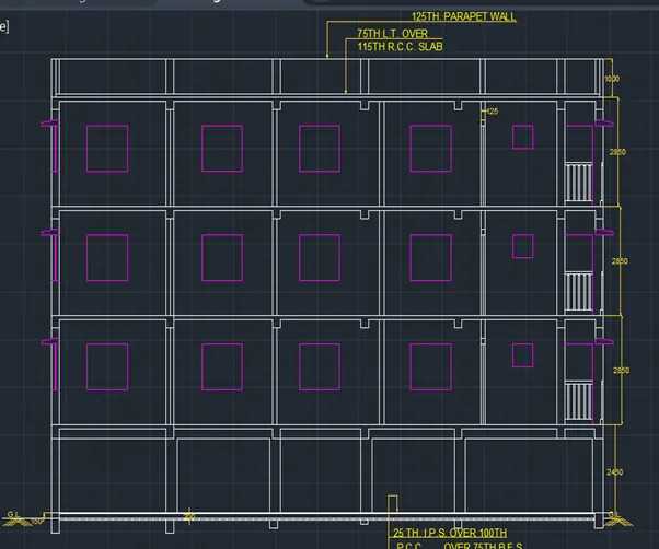
Fig. 111
- Annotation command was used to give the details related to section in the text.
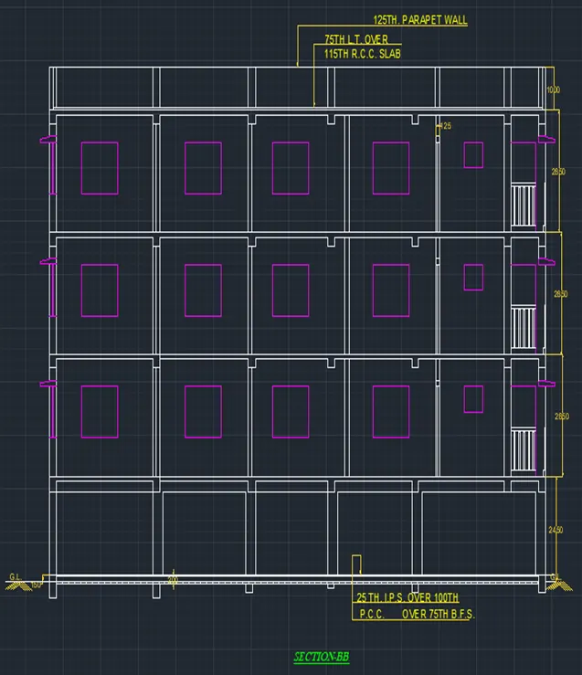
Fig. 112