Creating a Layout, Section and Elevation with dimensions using AutoCad
AIM : 1. Create the Plan and Sections as shown in the Figures. Use proper dimension techniques and dimension styles to document the project. Assume the sizes of the doors and windows as per construction standards. Refer to sections for stair details if required.
Introduction: In this challenge i have draft the above meationed drawing i.e, The Plan and Sections as shown in the Figures, using AutoCad. here in this challange i have attached all the drawings in a image format and with the proper procedure as possible.
The comman commands which are used in this challange are discussed below
Selecting of Tools:
- Line: Ribbon< Home< Line, Command: Line or L, Home< Draw< Line.
- Polyline: Ribbon< Home< Polyine, Command: polyline or pl, Home< Draw< polyline.
- Rectangle: Ribbon< Home< rectangle, Command: rectangle or rec, Home< Draw< rectangle.
- Ploygon: Ribbon< Home< Ploygon, Command: Ploygon or pol, Home< Draw< Ploygon.
- Circle: Ribbon< Home< Circle, Command: Circle or C, Home< Draw< Circle.
- Fillet: Ribbon< Home< Fillet, Command: Fillet or F, Home< modify< Fillet.
- Chamfer: Ribbon< Home< Chamfer, Command: Chamfer or cha, Home< modify<Chamfer.
- Move: Ribbon< Home< move, Command: move or M, Home< modify<Move.
- Copy: Ribbon< Home< Copy, Command: Copy or co, Home< modify<Copy.
- TRIM: Ribbon< Home< trim, Command: TRIM or TR, Home< modify<TRIM. etc
Question 1:
Create the Plan and Sections as shown in the Figures. Use proper dimension techniques and dimension styles to document the project. Assume the sizes of the doors and windows as per construction standards. Refer to sections for stair details if required.
ANS: Here i have attached the image which i have made in autocad 2019,
Procedure:
Step 1: for creating the above shown plan of a 4 flat appartment, using line tool in autocad is discussed below,
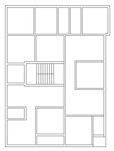
- open autocad 2019 and select a new file and saved as challange 5 and saved in the skill-lync folder.
- set the unit of drawing by giving command un in command and selected Engineering with precion 0'-0.0".
- select limit by giving command limmax and giving the limit 20',20' and entre.
- adjust the dimension size by giving command d and selecting the same unit as mentioned that is Engineering.
- Select the XL command and draft the two lines a vertical and horizontal and interset each other.
- Select the offset option and given the data as shown in the images.
- After giving the proper offset trim the excess.
- Give the command panel and select the trim option and trim the excess.
- creat a plan as shown in the question.
Step 2: Creating the layers in autocad is discussed below,
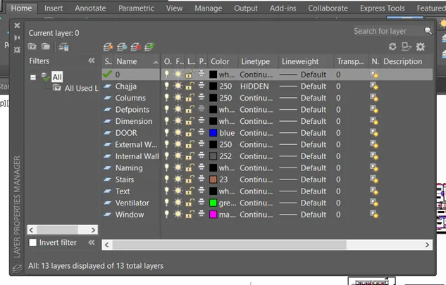
- Go to the ribbon panel select the layers properties
- Select the add new layer option.
- Edit the layer as I have given layer as doors, windows, external wall, internal wall etc..
- cretaing a layer that is go for a option create new layer.
- and now select the layer and right click and select as rename option and give the names.
- the names i have used as Door, window, ventilator wall etc.
- assign proper properties and colour which ever u like.
- Edit the required layers as wanted as shown in the above image.
Step 3: Creation of Columns and placing the columns in proper position in autocad is discussed below,
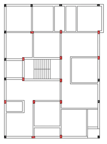
- Use Rectangle option and give the size as 9"x12" as shown in above figure.
- Hatch the created rec by using hatch command and select the concrete hatch with 100 as scale factor.
- Chose the colour in this i have selected black colour.
- Bolock the creted rec by using the command block and select the base point and select the component and give the name.
- I have given the name Column 9x12 in this drawing.
- and use copy tool and place the column in the proper position and alignment as shown in the figure.
- simillarly create another column with the dimension 9"x18" as shown in figure.
- use array tool and use path with proper spacing by selecting 3 components as shown above.
- use the line tool and draw the stirrup and is anchor as shown.
Step 4: Placing of Doors and Windows in proper position,
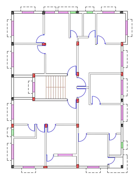
- create a door of size 900, 1000, 750mm of three types as shown.
- draw a line of size 900 and thick it by using ofset and use circle tool as shown.
- trim the excess of the circle and that is how u create a door
- Hatch the created rec by using hatch command and select the concrete hatch with 100 as scale factor.
- Chose the colour in this i have selected black colour.
- Bolock the creted door by using the command block and select the base point and select the component and give the name.
- I have given the name door d1 in this drawing.
- and use copy tool and place the column in the proper position and alignment as shown in the figure.
- simillarly create 2 more doors that is 1000mm and 750mm as shown in figure.
- And give name as D2& D3 respectivilly.
- after creating the doors and windows place it in proper position as shown.
Step 5: Completion of plan with proper naming and Dimension,
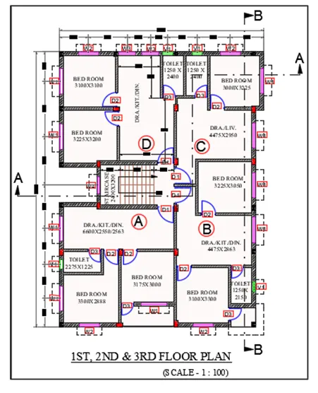
- After placing of doors and window now the time is for naming.
- select the Mtext and select the type of font colour and size of text and type the content what u want to show.
- after creating the prper name copy it by all the places where we want.
- Use move tool and place all the drawings drawn in the proper places.
- use Mtext option and type which ever required or shown.
- after editing the text copy the text and placed in columns or where ever required as shown above.
- edit the copied text by giving commant textedit and star editing the copied text.
- Now give the dimension as shown by using dimlinear command and give proper dimension.
- use dimcontinue option and place it where required.
- and now hatch the walls with using brick wall option and place in proper position.
Step 6: Creation of Section A-A of the above showing plan.
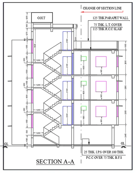
- use xl command and select the plan that is edges of doors windows column and ventilator if showing.
- create a line as a ground floor line and trim the excess.
- draw the doors an windows if showing using line tool or trimming the extra lines.
- after completion of the gf now the whole section is copied and place as one above the other,
- as 3 floors are simmilar in plan and dimension so copy it.
- after copieng give proper naming that is by using mtext option.
- select the Mtext and select the type of font colour and size of text and type the content what u want to show.
- after creating the prper name copy it by all the places where we want.
- Use move tool and place all the drawings drawn in the proper places.
- use Mtext option and type which ever required or shown.
- after editing the text copy the text and placed in columns or where ever required as shown above.
- edit the copied text by giving commant textedit and star editing the copied text.
- Now give the dimension as shown by using dimlinear command and give proper dimension.
- use dimcontinue option and place it where required.
- and now hatch the walls with using brick wall option and place in proper position.
Step 6: Creation of Section of B-B of the above showing plan.
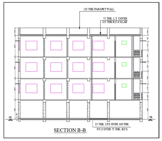
- use xl command and select the plan that is edges of doors windows column and ventilator if showing.
- create a line as a ground floor line and trim the excess.
- draw the doors an windows if showing using line tool or trimming the extra lines.
- after completion of the gf now the whole section is copied and place as one above the other,
- as 3 floors are simmilar in plan and dimension so copy it.
- after copieng give proper naming that is by using mtext option.
- select the Mtext and select the type of font colour and size of text and type the content what u want to show.
- after creating the prper name copy it by all the places where we want.
- Use move tool and place all the drawings drawn in the proper places.
- use Mtext option and type which ever required or shown.
- after editing the text copy the text and placed in columns or where ever required as shown above.
- edit the copied text by giving commant textedit and star editing the copied text.
- Now give the dimension as shown by using dimlinear command and give proper dimension.
- use dimcontinue option and place it where required.
- and now hatch the walls with using brick wall option and place in proper position.
Result:
The above shown diagram is of the plan or appartment which include four flats that is2 numbers of 2BHK and 2 numbers of 1BHK as shown in the plan it is of 3 floors with parking in the Ground Floor,
A complete plan with proper section is discussed above.
The Autocad drawing file is attached please go through it.