Creating a Layout, Section and Elevation with dimensions using AutoCad
AIM - Creating a Layout, Section and Elevation with dimensions using AutoCad
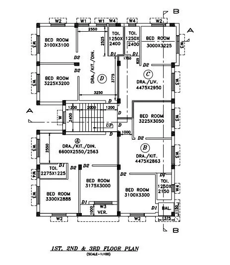
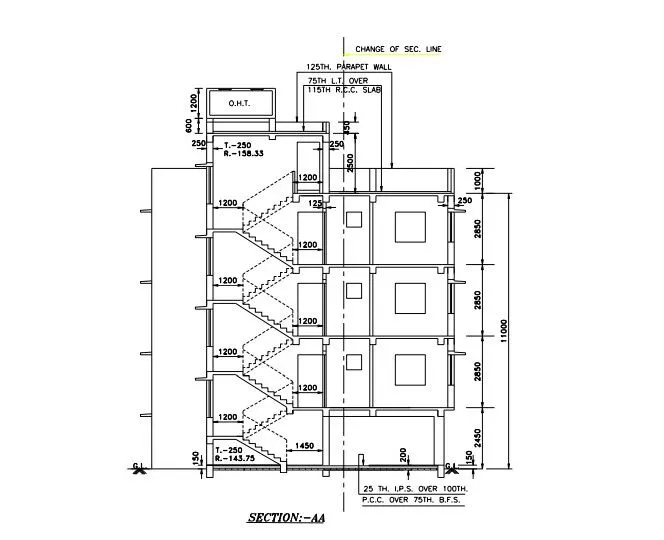
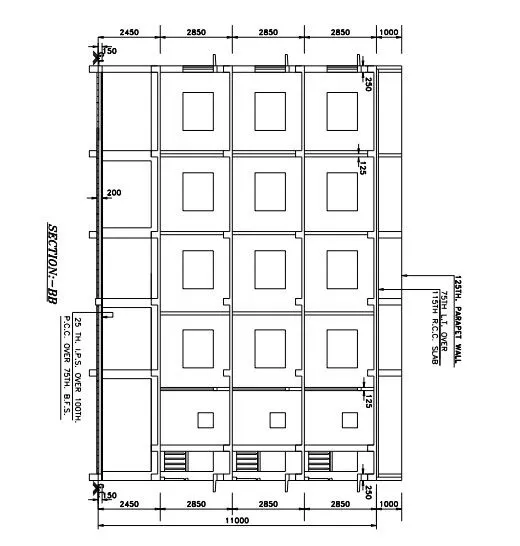
Q1. Create the Plan and Sections as shown in the Figures. Use proper dimension techniques and dimension styles to document the project. Assume the sizes of the doors and windows as per construction standards. Refer to sections for stair details if required.
Procedure -
Type UN and press enter
Under Drawing Units, select decimal
Now the lower limit is set to 0, 0 and upper limit to 100000, 100000
Type Z enter to zoom and A enter to all
1. Exterior walls
To create a Layer
In the Layer Properties Manager, click New Layer.
A layer name is added to the layer list.
Enter a new layer name as walls by typing over the highlighted layer name.
Select a suitable colour for that layer
Using the construction line command XL horizontal and vertical lines was created. As the thickness of external walls is 250, an offset of 250 was created both vertically and horizontally. The edges and corners are trimmed off or filleted.
The horizontal outer line is offsetted to a distance of 11850.
This line is again offsetted to a distance of 250 that is the wall thickness
The vertical outer line is offsetted to a distance of 16138.
This line is again offsetted to a distance of 125 that is the wall thickness
The edges and corners are trimmed off or filleted to get the following image
2. Interior walls
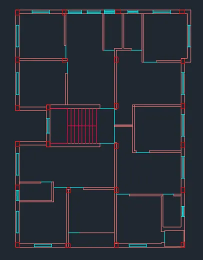
According to the plan the internal walls are drafted by off setting the external walls as required and the thickness of internal walls is taken as 125. The edges and corners after trimming or filleting the following image is obtained
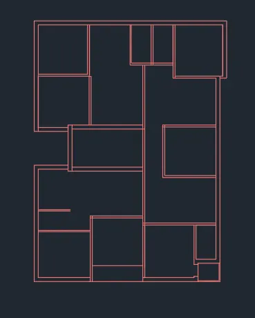
3. openings
Now using the line and trim command all the openings in interior and exterior walls was made for doors or for steps and the resultant image obtained is as follows.
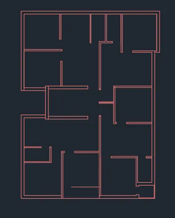
4. Columns
To create a Layer for columns
In the Layer Properties Manager, click New Layer.
A layer name is added to the layer list.
Enter a new layer name as Columns by typing over the highlighted layer name.
Select a suitable colour for that layer
Using the rectangle command a column of size 250x400 was drawn and placed at positions necessary and as shown in figure.
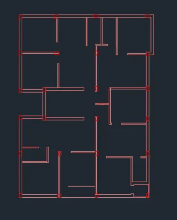
5. Window and doors
To create a Layer for windows and doors
In the Layer Properties Manager, click New Layer.
A layer name is added to the layer list.
Enter a new layer name as windows and doors by typing over the highlighted layer name.
Select a suitable colour for that layer
By using the line, offset, trim and fillet commands all the doors and windows was created and placed as in plans.
The size of doors and windows was assumed as per standard dimentions and is as follows:
D-1000
D1-750
D2-900
W-1000
W1-900
W2-1200
W3-1500
W4-700
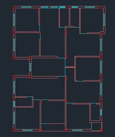
7. Staircase portion
The staircase portion was then drawn next using tools like line, offset, fillet and trim. As for dimensions thread was taken as 250mm and rise of 150mm
8. Dimensions
To create a Layer for Dimensions
In the Layer Properties Manager, click New Layer.
A layer name is added to the layer list.
Enter a new layer name as Dimensions by typing over the highlighted layer name.
Select a suitable colour for that layer.
By typing the D command for dimension style manager the overall scale of 75 was applied and in text alignment section aligh with dimension line was chosen.
9. Texts
To create a Layer for texts
In the Layer Properties Manager, click New Layer.
A layer name is added to the layer list.
Enter a new layer name as text by typing over the highlighted layer name.
Select a suitable colour for that layer.
Using ST command, the text style manager a suitable font- Tempus sans and height of text 250mm was specified and was set as current and all.
All the texts which are to be entered and was typed and doted lines was provided at places necessary
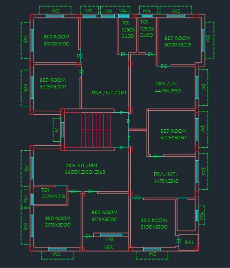
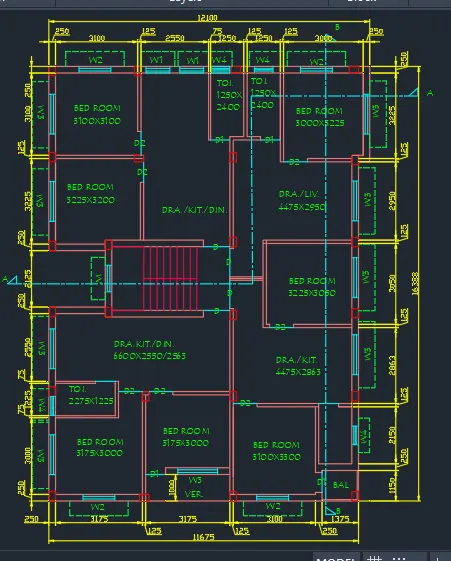
Result - The plan layout is now completed
SECTION AA
Using the XL command for construction lines, the projection of all the walls and columns which are coming in the section was taken first.
The height of the floors was taken accordingly as in plan.
G.F-2450mm
1st Floor-2850mm
2nd Floor-2850mm
3rd Floor-2850mm
Slab thickness was taken as 125 mm
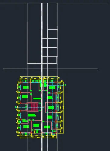
Now all the unwanted lines was trimmed off and a base outline of the section is as given
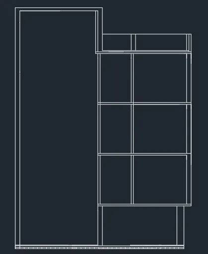
The windows and doors lines was now projected using the construction line tool and are drawn as per the dimensions as follows
W2-1200x1200
W4-700x500
D-1000x2000
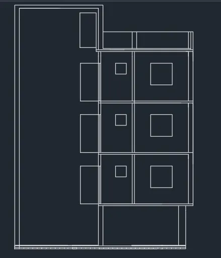
Now all the windows which are coming in the wall section was drawn and their sunshade was also drawn at this point. The dimensions of the windows is as follows
W3-1500x1200
W-1000x1500
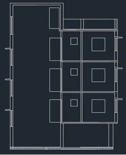
The staircase was designed next.
The dimensions of steps from ground floor to 2nd floor is as follows
Thread-250mm
Riser-143.75mm
The 3rd floor dimension of step is as follows.
Thread-250
Riser-158.33.
Also all the beams which comes along the columns was also made for all floors as shown
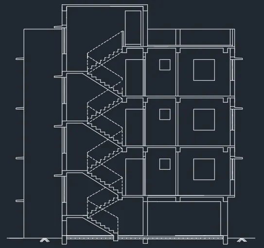
The parapet wall and the over head tank was designed next
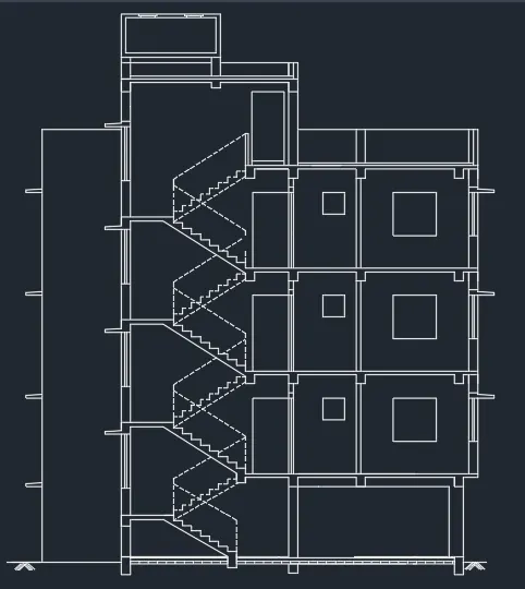
As all the parts of section are now done, the dimensioning was done next.
The dimensions layer was set for this and the step was completed as shown.
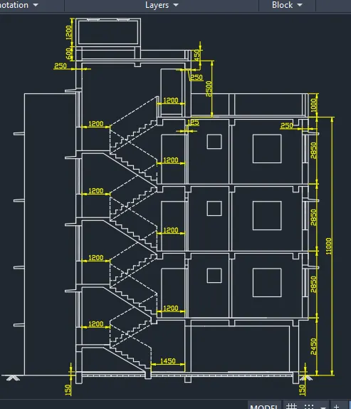
The final step is providing the texts where ever necessary.
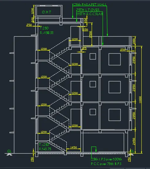
Result - The section AA is now completed.
SECTION BB
Using the XL command for construction lines, the projection of all the walls and columns which are coming in the section BB was taken first.
The height of the floors was taken accordingly as in plan.
G.F-2450mm
1st Floor-2850mm
2nd Floor-2850mm
3rd Floor-2850mm
Slab thickness was taken as 125 mm
And other room dimensions was taken as per the plan
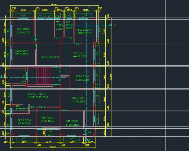
Few of the unwanted lines are now trimmed off.
All the general outline for walls are now drawn for each floor
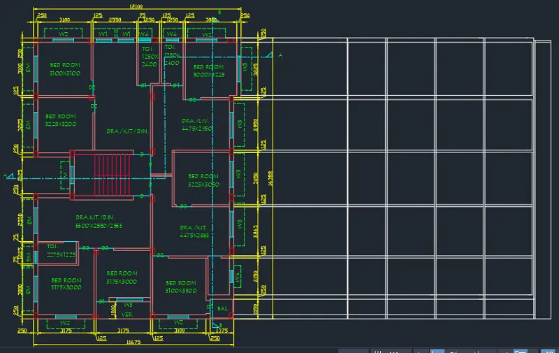
All unwanted lines are now trimmed off,and next the windows was drawn as shown. Now a rough outline sketch of the section is obtained.
Window sill level was taken as 800mm and lintel level as 2300mm
Window size is as follows:
W3-1500x1200
W4-700x500
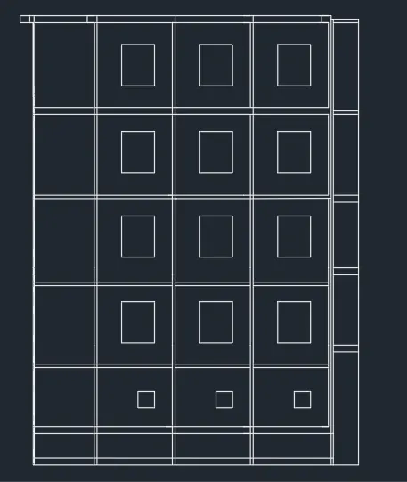
The beams are provided where ever necessary as per the plan as shown and this was done with the help of rectangle command.
The sunshade is also drawn as required and the section BB is now complete
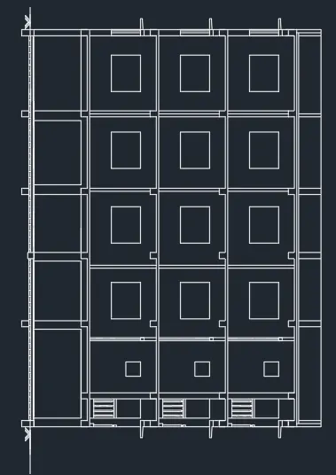
As all the parts of section are now done, the dimensioning was done next.
The dimensions layer was set for this and the step was completed as shown.
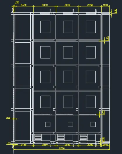
The final step is providing the texts where ever necessary.
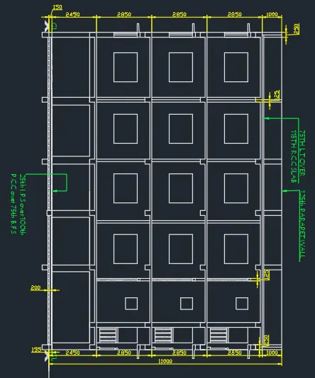
Result - The section BB is now completed.