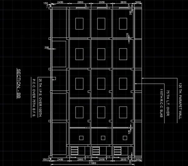
Creating a Layout, Section and Elevation with dimensions using AutoCad
EDITING DIMENSIONS
1)FLOOR PLAN
AIM: To create the floor plan using AutoCAD.
INTRODUCTION: The floor plan using AutoCAD is created by Lines. The procedure and result should be written after creating the floor plan.
PROCEDURE:
STEP 1:
- Open the AutoCAD software and click start Drawing tab.
- Enter UNITS in command box.
- Select DECIMAL in TYPE, 0 in PRECISION and MILLIMETERS in UNITS TO SCALE INSERTED CONTENT. Press OK.
- Switch on ORTHOMODE
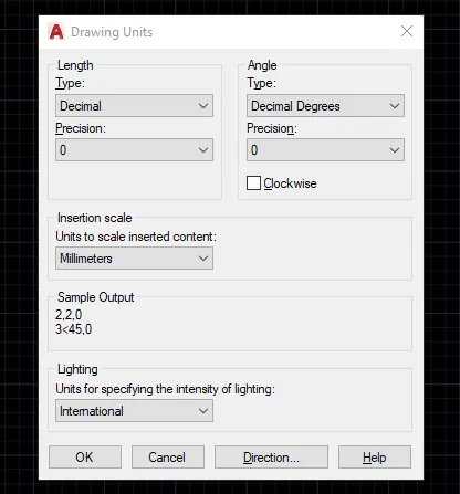
STEP 2:
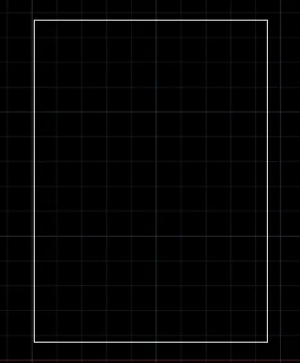
- Enter XL in command box and press ENTER
- Enter H and place the horizontal line in workspace
- Enter XL in command box and press ENTER
- Enter V and place the vertical line in workspace
- Enter O in command box and press ENTER
- Enter 11705 as offset distance
- Click the vertical line and place at 11705 mm distance
- Enter O in command box and press ENTER
- Enter 16283 as offset distance
- Click the horizontal line and place at 16283 mm distance
- Enter TR in command box and press ENTER twice
- Delete the unwanted lines
STEP 3:
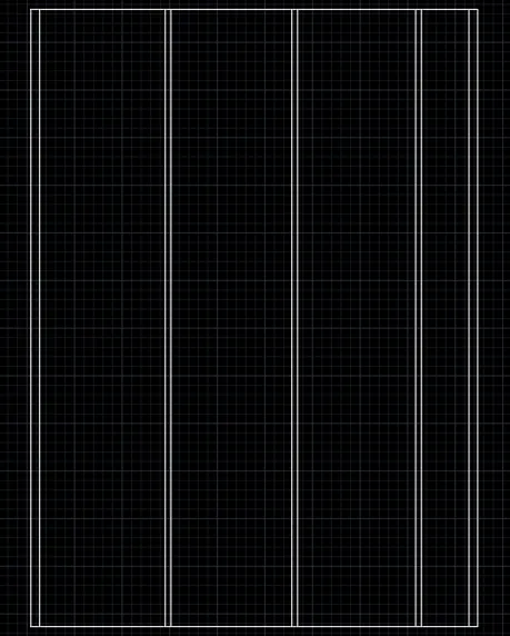
- Enter O in command box and press ENTER
- Enter 230 as offset distance
- Select the left side vertical line and place offset line inwards
- Select the right-side vertical line and place offset line inwards
- Enter O in command box and press ENTER
- Enter 3300 as offset distance
- Select the left side vertical line and place offset line inwards
- Enter O in command box and press ENTER
- Enter 150 as offset distance
- Select the 3300 vertical line and place offset line inwards
- Enter O in command box and press ENTER
- Enter 3175 as offset distance
- Select the 150 vertical offset line and place offset line inwards
- Enter O in command box and press ENTER
- Enter 150 as offset distance
- Select the 3175 vertical line and place offset line inwards
- Enter O in command box and press ENTER
- Enter 3100 as offset distance
- Select the 150 vertical offset line and place offset line inwards
- Enter O in command box and press ENTER
- Enter 150 as offset distance
- Select the 3100 vertical line and place offset line inwards
STEP 4:
- Enter O in command box and press ENTER
- Enter 230 as offset distance
- Select the upper horizontal line and place offset line inwards
- Select the lower horizontal line and place offset line inwards
- Enter O in command box and press ENTER
- Enter 2888 as offset distance
- Select the lower horizontal line and place offset line inwards
- Enter O in command box and press ENTER
- Enter 75 as offset distance
- Select the 2888 offset line and place it inwards
- Enter O in command box and press ENTER
- Enter 1225 as offset distance
- Select the 75 offset line and place it inwards
- Enter O in command box and press ENTER
- Enter 75 as offset distance
- Select the 1225 offset line and place it inwards
- Enter O in command box and press ENTER
- Enter 2550 as offset distance
- Select the 75 offset line and place it inwards
- Enter O in command box and press ENTER
- Enter 230 as offset distance
- Select the 2250 offset line and place it inwards
- Enter O in command box and press ENTER
- Enter 2215 as offset distance
- Select the 230 offset line and place it inwards
- Enter O in command box and press ENTER
- Enter 230 as offset distance
- Select the 2215 offset line and place it inwards
- Enter O in command box and press ENTER
- Enter 3200 as offset distance
- Select the 230 offset line and place it inwards
- Enter O in command box and press ENTER
- Enter 230 as offset distance
- Select the 3200 offset line and place it inwards
- Enter O in command box and press ENTER
- Enter 3100 as offset distance
- Select the 230 offset line and place it inwards
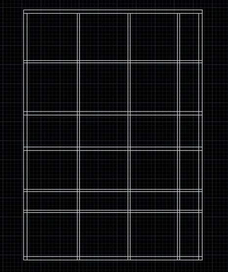
STEP 5:
- Enter O in command box and press ENTER
- Type 2275 as offset distance
- Click the inner left side vertical line and place it inwards
- Enter O in command box and press ENTER
- Type 150 as offset distance
- Click the 2275 vertical line and place it inwards
- Enter TR in command box
- Press ENTER twice
- Delete the unwanted lines
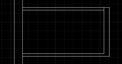
- Enter O in command box
- Type 500 as offset distance
- Select the inner line of 230 mm width and place it inside.
- Enter TR in command box
- Delete the unwanted lines
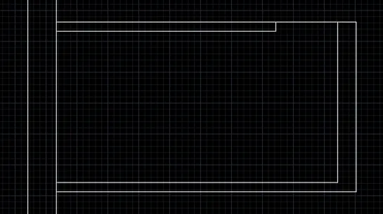
STEP 6:
- Enter O in command box
- Type 50 as offset distance
- Select the lower inside line and place it inwards
- Enter O in command box
- Type 1000 as offset distance
- Select the lower outer line and place it inwards
- Enter O in command box
- Type 230 as offset distance
- Select the 1000 mm line and place it inwards
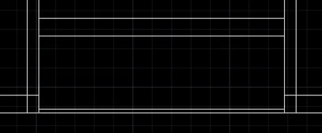
STEP 7:
- Enter O in command box
- Type 3000 as offset distance
- Select the inner line of lower part and place it inside
- Enter O in command box
- Type 150 as offset distance
- Select 3000 mm line and place it outside
- Enter O in command box
- Type 520 as offset distance
- Select the inner line of 3300 mm and place it inside
- Enter TR in command box
- Delete the unwanted lines
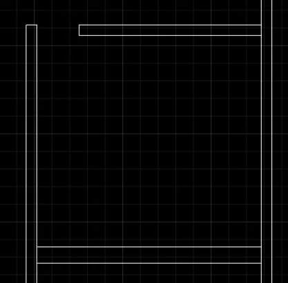
- Enter O in command box
- Type 500 as offset distance
- Select the inner line of 3300 mm and place it inside
- Enter TR in command box
- Delete the unwanted lines
- Enter REC in command box
- Click DIMENSIONS in command box
- Enter 230 as length
- Enter 400 as width
- Place it at 3300 mm offset line
- Enter CO in command box
- Copy the rectangle to right side
- Switch off ORTHOMODE
- Copy the rectangle to diagonally opposite side
- Copy the rectangle and place it aside
- Enter RO in command box
- Enter 90 as angle
- Enter M in command box
- Move the rectangle to lower part of first rectangle
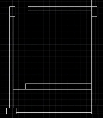
- Enter O in command box
- Enter 438 as offset distance
- Select the 230 mm vertical line and place it inwards
- Enter O in command box
- Enter 1800 as offset distance
- Select the 438 mm vertical line and place it inwards
- Enter L in command box
- Trace the line downwards and type 85
- Connect it to other side
- Enter O in command box
- Enter 50 as offset distance
- Select the 85 mm line and place it downwards
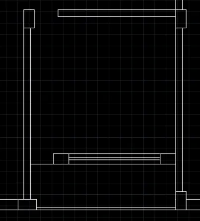
STEP 8:
- Enter O in command box
- Enter 1000 as offset distance
- Select the inside left line and place it inwards
- Enter O in command box
- Enter 1000 as offset distance
- Select the 1000 mm line and place it inwards
- Enter L in command box
- Trace the line downwards and type 85
- Connect it to other side
- Enter O in command box
- Enter 50 as offset distance
- Select the 85 mm line and place it downwards
- Enter O in command box
- Enter 300 as offset distance
- Select the inside lower line and place it upside
- Enter O in command box
- Enter 700 as offset distance
- Select the 300 mm line and place it upside
- Enter O in command box
- Enter 1500 as offset distance
- Select the 700 mm line and place it upside
- Enter O in command box
- Enter 843 as offset distance
- Select the 1500 mm line and place it inwards
- Enter O in command box
- Enter 500 as offset distance
- Select the 843 mm line and place it inwards
- Enter O in command box
- Enter 400 as offset distance
- Select the 500 mm line and place it inwards
- Enter O in command box
- Enter 557 as offset distance
- Select the 400 mm line and place it inwards
- Enter O in command box
- Enter 1500 as offset distance
- Select the 557 mm line and place it inwards
- Enter L in command box
- For first rectangle, trace the line vertically
- Enter 100 as first point
- Enter 500 as next point
- Enter 1700 as next point and close it
- Enter CO in command box
- Select the sunshade and place it on another 1500 mm rectangle
- Enter L in command box
- For middle rectangle, trace the line vertically
- Enter 100 as first point
- Enter 500 as next point
- Enter 700 as next point and close it.
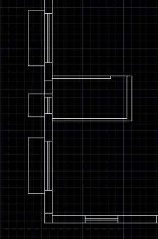
STEP 9:
- Enter O in command box
- Type 1996 as offset distance
- Select the inner line and place it inwards
- Enter O in command box
- Type 230 as offset distance
- Select the 1996 mm line and place it inwards
- Rectangle of 230mm x 400mm size is copied and placed at opposite wall
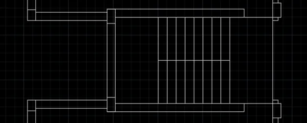
- Enter L in command box
- Click the lower part of rectangle and connect it with 1996 mm line
- Enter O in command box
- Type 2400 as offset distance
- Select the line and place it inwards
- Enter O in command box
- Type 230 as offset distance
- Select the 2400 and place it inwards on upper side and downside
- Copy and paste the rectangles on required place
- Enter O in command box
- Type 1200 as offset distance
- Select the 1996 mm line and place it inwards
- Enter O in command box
- Type 2000 as offset distance
- Select the 1200 mm line and place it inwards
- Enter O in command box
- Type 250 as offset distance
- Select the 1200 mm line and place it inwards
- Repeat the above step for 6 more times
- Enter TR in command box
- Delete the unwanted lines
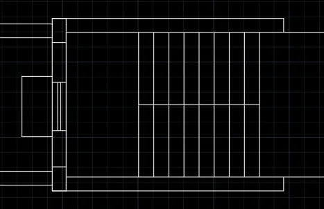
- Enter O in command box
- Type 660 as offset distance
- Select the rectangle lower part and place it inwards
- Enter O in command box
- Type 800 as offset distance
- Select the 660 mm line and place it inwards
- Enter L in command box
- Enter 100 vertically and 500 horizontally
- Enter 1000 as vertical point
- Enter 85 as next point
- Enter O in command box
- Type 50 as offset distance
- Select the 85 mm line and place it inwards
STEP 10:
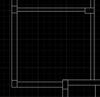
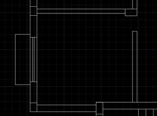
- Enter O in command box
- Enter 3225 as offset distance
- Select the inner line and place it
- Enter O in command box
- Enter 150 as offset distance
- Select the 3225mm line and place it
- Copy and place the rectangles wherever required
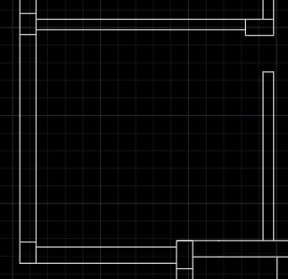
- Enter O in command box
- Enter 520 as offset distance
- Select the inner horizontal line and place it
- Enter TR in command box
- Delete the unwanted lines
- Enter CO in command box
- Copy the window with sunshade and place it
STEP 11:
- Enter O in command box
- Enter 3100 as offset distance
- Select the inner line and place it
- Enter O in command box
- Enter 150 as offset distance
- Select the 3100 mm line and place it
- Enter O in command box
- Enter 520 as offset distance
- Select the upper line of bed room and place it
- Copy the window with sunshade and place it
- Enter TR in command box
- Delete the unwanted lines
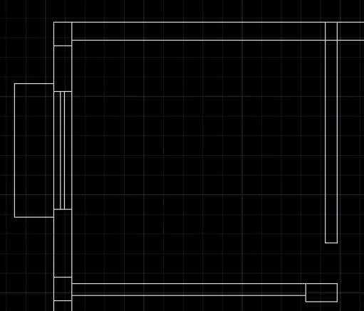
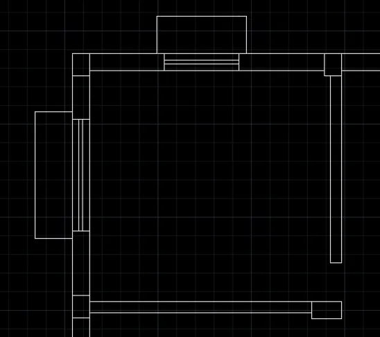
- Copy the window with sunshade from the first room and place it here
STEP 12:
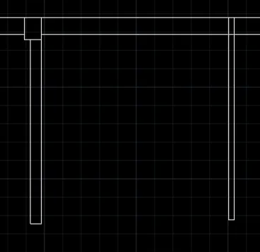
- Enter O in command box
- Enter 2550 as offset distance
- Select the inner line and place it
- Enter O in command box
- Enter 75 as offset distance
- Select the 2550 mm line and place it
STEP 13:
- Enter O in command box
- Enter 25 as offset distance
- Select the inner line and place it
- Enter O in command box
- Enter 800 as offset distance
- Select the 25 mm line and place it
- Enter L in command box and enter 85
- Enter 50 mm offset line and place it
- Copy the window and place at 1650 mm distance

- Enter L in command box
- Enter 100 as first point
- Enter 500 as next point
- Enter 1000 as next point
- Close the line
- Enter L in command box
- Enter 100 as first point
- Enter 500 as next point
- Enter 1800 as next point
- Close the line
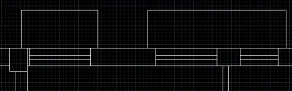
- Copy the window and create sunshade
- Enter L in command box
- Enter 3775 as first point
- Enter 150 as next point
- Enter O in command box
- Enter 1250 as offset distance
- Place it at 1250 distance from the selected line
- Connect the 3775mm line with this
- Enter O in command box
- Enter 75 as offset distance
- Enter O in command box
- Enter 75 as offset distance
- Enter O in command box
- Enter 1250 as offset distance
- Place it at 1250 distance from the selected line
- Enter O in command box
- Enter 500 as offset distance
- Enter TR in command box
- Delete the unwanted lines
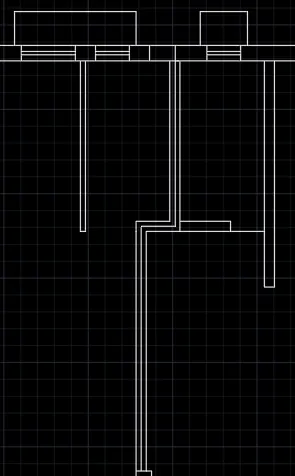
STEP 14:
- Copy the window with sunshade and place it
- Enter O in command box
- Enter 3225 as offset distance and place it
- Enter L in command box
- Enter 430 as first point and close it
- Enter 230 as offset distance and place it
- Enter TR and delete the unwanted lines
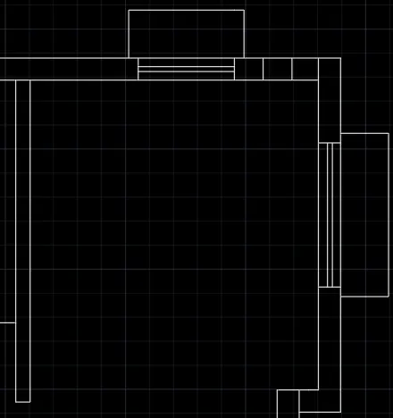
- Enter O in command box
- Enter 520 as offset distance and place it
- Enter TR and delete the unwanted lines
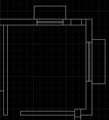
STEP 15:
- Enter O in command box
- Enter 2950 as offset distance and place it
- Enter O in command box
- Enter 150 as offset distance and place it
- Enter O in command box
- Enter 75 as offset distance and place it
- Enter TR in command box
- Delete all the unwanted lines
- Copy and place the window
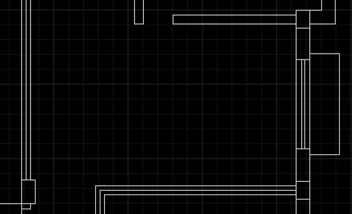
STEP 16:
- Enter O in command box
- Enter 3050 as offset distance and place it
- Enter O in command box
- Enter 150 as offset distance and place it
- Enter O in command box
- Enter 3225 as offset distance and place it horizontally
- Enter O in command box
- Enter 150 as offset distance and place it behind the 3225 mm line
- Connect the line with the stairs line
- Create 75 mm offset on the connecting line
- Enter O in command box
- Enter 520 as offset distance and place it horizontally
- Enter TR and delete all the unwanted lines
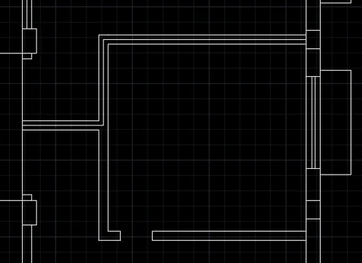
STEP 17:
- Enter O in command box
- Enter 2863 as offset distance and place it
- Enter O in command box
- Enter 150 as offset distance and place it
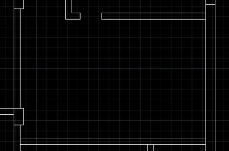
- Copy the window with sunshade and place it
- Copy the columns and place it
- Enter O in command box
- Enter 520 as offset distance and place it
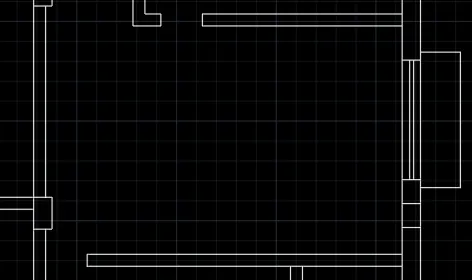
STEP 18:
- Enter O in command box
- Enter 3100 as offset distance and place it
- Enter O in command box
- Enter 150 as offset distance and place it
- Enter O in command box
- Enter 500 as offset distance and place it
- Enter O in command box
- Enter 2150 as offset distance and place it
- Enter O in command box
- Enter 230 as offset distance and place it
- Enter TR and delete all the unwanted lines
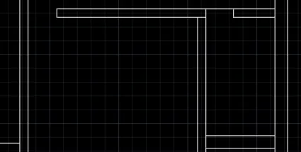
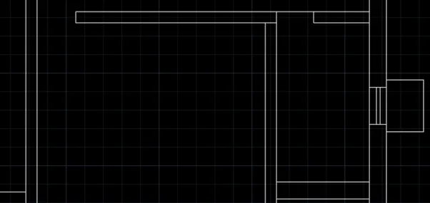
- Copy the window with sunshade from the first room
- Place it in the wall of 230 mm thickness
STEP 19:
- Enter O in command box
- Enter 50 as offset distance and place it
- Enter O in command box
- Enter 1150 as offset distance and place it vertically
- Enter O in command box
- Enter 1375 as offset distance and place it horizontally
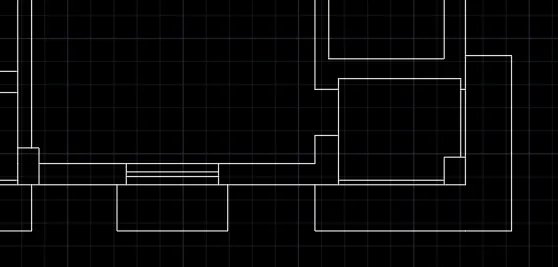
- Connect the wall on the rectangular box
- Copy the column and place on the wall
- Enter TR and delete all the unwanted lines
- Enter L in command box
- Enter 100 as first point
- Enter 500 as next point
- Enter 2130 as next point
- Enter 1900 as next point
- Close the line
- Copy and place the window with sunshade
STEP 20:
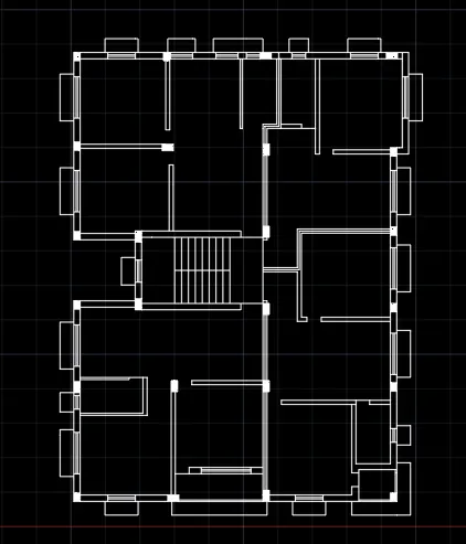
- Enter H in command box
- Select AR-SAND pattern
- Select 1 as scale
- Pick points on the columns
- Press ENTER
STEP 21:
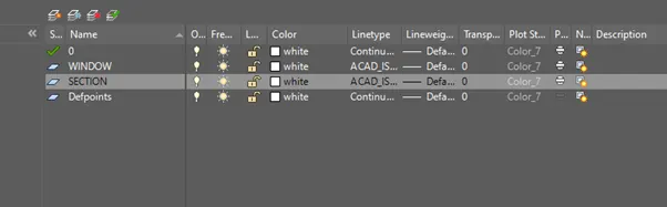
- Select LAYER PROPERTIES from the ribbon
- Select NEW LAYER
- Enter WINDOW and SECTION in NAME
- Select ISO dash for windows
- Select ISO long dash short dash for section
STEP 22:
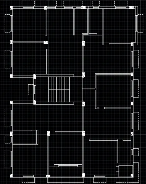
- Select the windows
- Click window in layer
STEP 23:
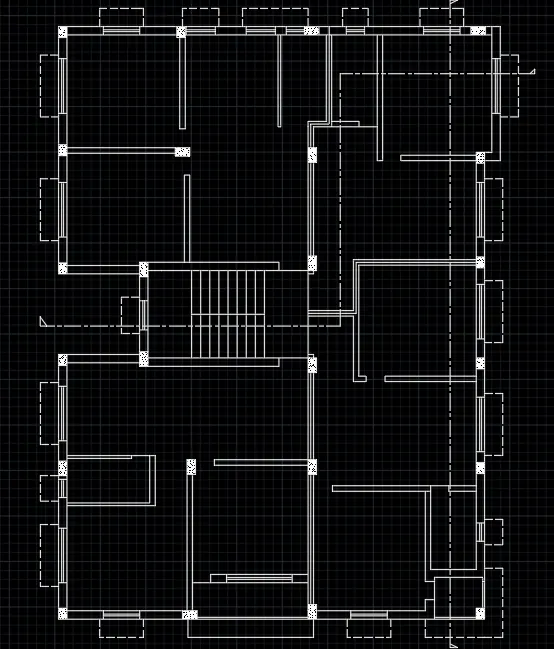
- Enter L in command box
- Draw the line as per the drawing
- Click the line
- Select the section in layer
STEP 24:
- Enter DIMS in command box
- Click MODIFY. In SYMBOLS and ARROWS, Enter ARROW SIZE as 200.
- In TEXT, Enter TEXT HEIGHT as 200.
- In PRIMARY UNITS, Click DECIMAL in UNIT FORMAT, 0 in PRECISION.
- In LINES, Enter 10 as EXTEND BEYOND LINES and 20 as OFFSET FROM ORIGIN. Click OK.
- Click SET CURRENT. Click CLOSE.
- Click DIMENSIONS AND TEXT dropdown in LAYER.
- Enter DIML in command box and drag the dimensions.
- Enter DT in command box. Enter 200 as TEXT HEIGHT and 0 as TEXT ROTATION ANGE.
- Enter TEXT.
- Enter CO in command box. Copy the text and place it in another location.
- Enter TEXTEDIT in command box. Using this, editing in text can be done.
- Click the layers to give their properties in diagrams
- Save the drawing and rename it as AUTOCAD CHALLENGE 7
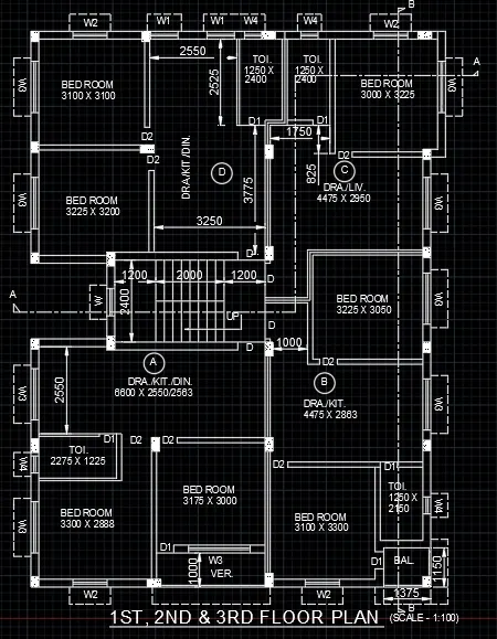
RESULT:
The floor plan is created by lines using AutoCAD. The step-by-step procedure for creating floor plan is also explained. The Dimension is also entered in the diagram
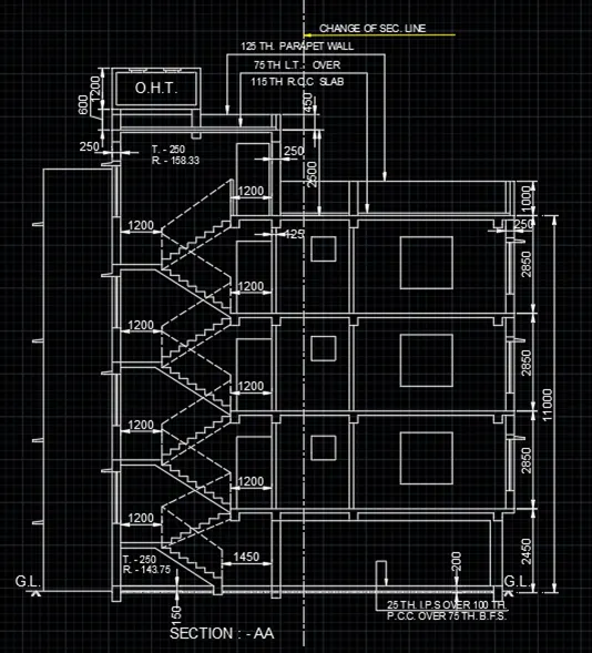
2)SECTION - AA
AIM: To create the section-AA using AutoCAD.
INTRODUCTION: The Section-AA using AutoCAD is created by Lines. The procedure and result should be written after creating the section-AA.
PROCEDURE:
STEP 1:
- Open the AutoCAD software and click start Drawing tab.
- Enter UNITS in command box.
- Select DECIMAL in TYPE, 0 in PRECISION and MILLIMETERS in UNITS TO SCALE INSERTED CONTENT. Press OK.
- Switch on ORTHOMODE
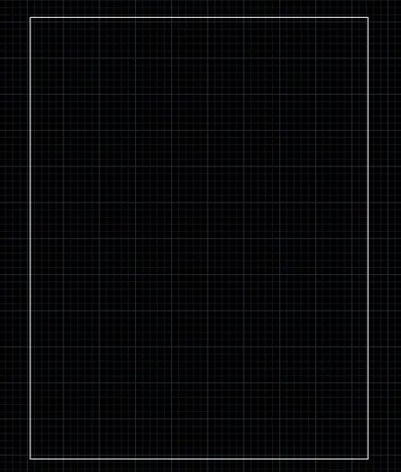
- Enter REC in command box
- Enter 11705 as length
- Enter 15300 as width
STEP 2:
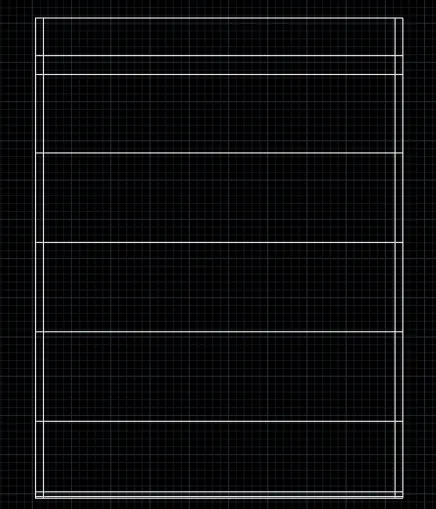
- Enter O in command box
- Enter 50 as offset distance and place it
- Enter O in command box
- Enter 200 as offset distance and place it
- Enter O in command box
- Enter 2450 as offset distance and place it
- Enter O in command box
- Enter 2850 as offset distance and place it
- Repeat it twice
- Enter O in command box
- Enter 2500 as offset distance and place it
- Enter O in command box
- Enter 600 as offset distance and place it
- Enter O in command box
- Enter 250 as offset distance and place it at left and right side.
- Enter O in command box
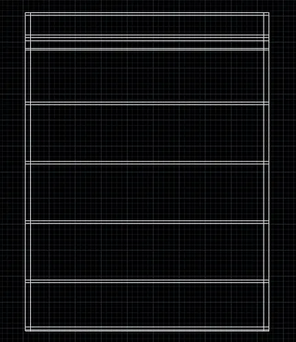
- Enter 125 as offset distance and place it inner side of top part
- Place it in lower part of 1200
- Enter O in command box
- Enter 75 as offset distance and place it in upper part of 600
- Enter O in command box
- Enter 125 as offset distance and place it in below 2850
- Repeat the above step twice
- Enter O in command box
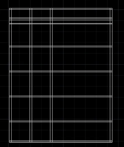
- Enter 2325 as offset distance and place it
- Enter O in command box
- Enter 2200 as offset distance and place it
- Enter O in command box
- Enter 125 as offset distance and place it after 2325
- Enter O in command box
- Enter 250 as offset distance and place it after 2200
STEP 3:
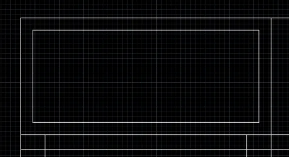
- Enter O in command box
- Enter 125 as offset distance and place it inside
- Enter F in command box
- Select the lines to create corners
- Enter TR and delete the unwanted lines
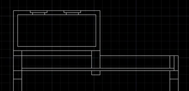
- Enter L in command box
- Enter 500 as first point
- Enter 63 as next point
- Enter 500 as next point
- Close the line
- Enter L in command box
- Enter 70 as first point
- Enter 63 as next point
- Enter 360 as next point
- Enter 63 as next point
- Enter CO in command box
- Copy the object and enter 500
STEP 4:
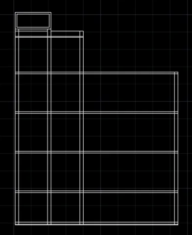
- Enter O in command box
- Enter 150 as offset distance and place it inside
- Enter TR in command box
- Delete the unwanted lines
STEP 5:
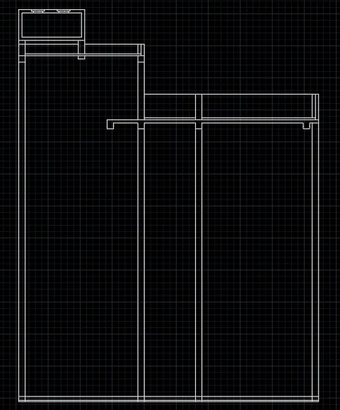
- Enter L in command box
- Enter 350 as first point
- Enter CO in command box
- Copy it other side
- Enter L in command box
- Enter 175 as first point
- Enter 250 as next point
- Enter 175 as next point
- Enter O in command box
- Enter 1000 as offset distance
- Enter O in command box
- Enter 1000 as offset distance
- Enter O in command box
- Enter 75 as offset distance and place above 2500
- Enter O in command box
- Enter 125 as offset distance and place between wall at right side
- Enter O in command box
- Enter 125 as offset distance and place below 1000
- Enter L in command box
- Enter 1200 as first point
- Enter 350 as next point
- Enter 250 as next point
- Close the line
- Repeat same step for 3 more times
- Enter TR and delete all the unwanted lines
- Enter CO in command box
- Copy the created walls thrice
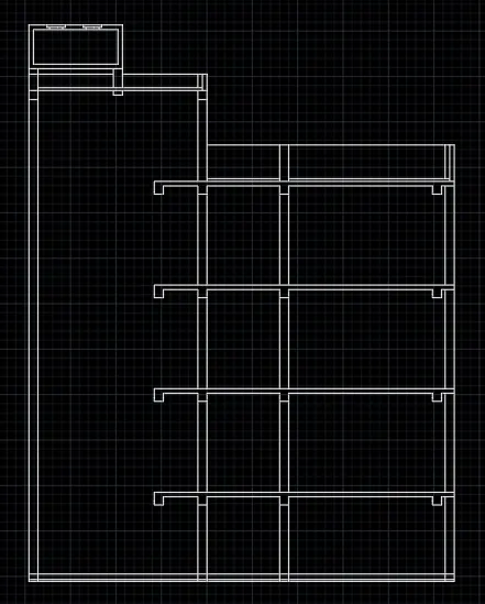
STEP 6:
- Enter O in command box
- Enter 75 as offset distance and place it
- Enter O in command box
- Enter 950 as offset distance and place it
- Enter O in command box
- Enter 100 as offset distance and place it
- Enter O in command box
- Enter 75 as offset distance and place it
- Enter O in command box
- Enter 1425 as offset distance and place it between 2850
- Enter O in command box
- Enter 150 as offset distance and place it after 1425
- Enter L in command box
- Connect two lines
- Enter CO in command box
- Copy the object at 2700mm and 5550 mm distance
- Enter O in command box
- Enter 125 as offset distance and place it after middle walls
- Enter TR and delete unwanted lines
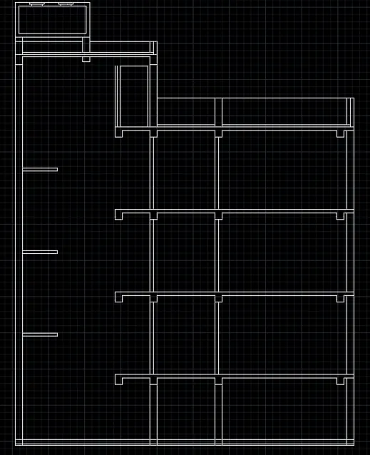
STEP 7:
- Switch off ORTHOMODE
- Enter L in command box
- Connect the landing and walls
- Switch on ORTHOMODE
- Enter 250 as tread and 158.33 as riser
- Connect it to 1200 mm landing
- Repeat the above step for upper part
- Switch on ORTHOMODE
- Enter L in command box
- Enter 1050 as first point
- Enter L in command box
- Enter 1050 as first point for 1200 landing
- Switch off ORTHOMODE
- Connect the 1050 mm lines with inclined lines
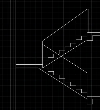
STEP 8:
- Enter CO in command box
- Copy the stairs
- Place it at three places
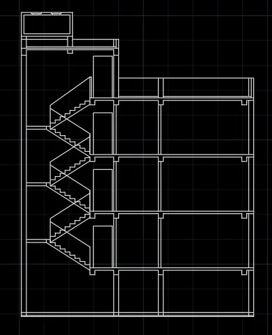
STEP 9:
- Enter O in command box
- Enter 863 as offset distance and place it behind 2850
- Enter O in command box
- Enter 150 as offset distance and place it behind 863 mm line
- Connect the landing and walls
- Switch on ORTHOMODE
- Enter 250 as tread and 143.75 as riser
- Connect it to 1200 mm landing
- Repeat the above step for upper part
- Switch on ORTHOMODE
- Enter L in command box
- Enter 1050 as first point
- Enter L in command box
- Enter 1050 as first point for 1200 landing
- Switch off ORTHOMODE
- Connect the 1050 mm lines with inclined lines
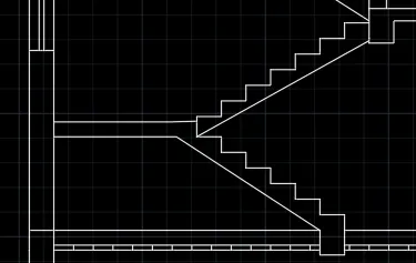
STEP 10:
- Enter O in command box
- Enter 558 as offset distance and place it
- Enter O in command box
- Enter 135 as offset distance and place it
- Enter O in command box
- Enter 1500 as offset distance and place it
- Switch off ORTHOMODE
- Enter L in command box
- Enter 500 as first point
- Enter 30 as next point
- Switch on ORTHOMODE
- Connect it to the wall
- Enter L in command box
- Enter 100 as first point
- Enter 50 as next point
- Enter TR and delete all the unwanted lines
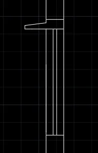
STEP 11:
- Enter CO in command box
- Copy the window and place it twice
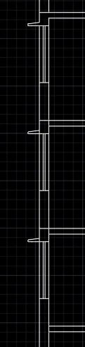
STEP 12:
- Enter O in command box
- Enter 200 as offset distance and place it many times reaching the opposite wall
- Enter L in command box
- Enter 350 as first point
- Enter 250 as next point
- Connect it to the walls
- Enter L in command box
- Enter 50 as first point
- Enter 250 as next point
- Connect it to the walls
- Enter L in command box
- Enter 50 as first point
- Enter 150 as next point
- Connect it to the walls
- Enter L in command box
- Enter 50 as first point
- Enter 350 as next point
- Connect it to the walls
- Enter TR and delete the unwanted lines

STEP 13:
- Enter L in command box
- Click on the wall and connect it to the floor
- Enter 350 as offset distance and connect it to the horizontal line
- Enter TR and delete the unwanted lines
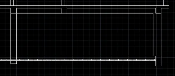
STEP 14:
- Enter CO in command box
- Place it some place
- Enter RO in command box
- Enter 270 angle
- Enter M in command box
- Move the window at opposite place
- Enter CO in command place
- Copy the window at two places

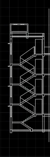
STEP 15:
- Enter L in command box
- Enter 5580 as first point
- Enter EXTEND in command box
- Extend the line to the extent
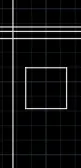
STEP 16:
- Enter REC in command box
- Enter 500 as first point
- Enter 700 as length
- Enter 700 as width
- Enter M and move it at 220 mm distance
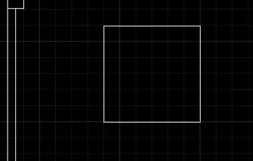
STEP 17:
- Enter REC in command box
- Enter 1500 as length
- Enter 1500 as width
- Enter M and move it at 1375 mm distance
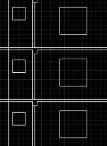
STEP 18:
- Enter CO in command box
- Copy the two squares
- Place it at two places
STEP 19:
- Switch off ORTHOMODE
- Enter L in command box
- Enter 500 as first point
- Copy it at 20 mm distance twice
- Enter MI in command box
- Mirror those three lines
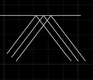
STEP 20:
- Enter L in command box
- Enter 2000 as first point
- Connect it with walls
- Copy the sunshade
- Place it at 3400 mm distance four times
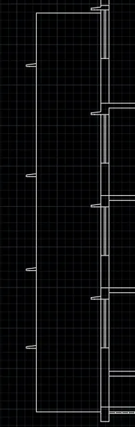
STEP 21:
- Select LAYER PROPERTIES
- Click NEW LAYER
- Enter STAIRS AND SECTION LINE in NAME
- Select ISO dash for stairs
- Select ISO long dash short dash for section line
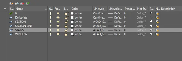
STEP 22:
- Select stairs and apply ISO dash line type
- Select section line and apply ISO dash
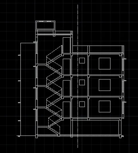
STEP 23:
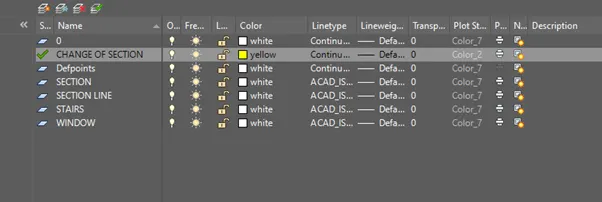
- Select LAYER PROPERTIES
- Click NEW LAYER
- Enter CHANGE OF SECTION in NAME
- Select YELLOW for COLOR
STEP 24:
- Enter DIMS in command box
- Click MODIFY. In SYMBOLS and ARROWS, Enter ARROW SIZE as 200.
- In TEXT, Enter TEXT HEIGHT as 200.
- In PRIMARY UNITS, Click DECIMAL in UNIT FORMAT, 0 in PRECISION.
- In LINES, Enter 10 as EXTEND BEYOND LINES and 20 as OFFSET FROM ORIGIN. Click OK.
- Click SET CURRENT. Click CLOSE.
- Click DIMENSIONS AND TEXT dropdown in LAYER.
- Enter DIML in command box and drag the dimensions.
- Enter DT in command box. Enter 200 as TEXT HEIGHT and 0 as TEXT ROTATION ANGE.
- Enter TEXT.
- Enter CO in command box. Copy the text and place it in another location.
- Enter TEXTEDIT in command box. Using this, editing in text can be done.
- Click the layers to give their properties in diagrams
- Save the drawing and rename it as AUTOCAD CHALLENGE 7
RESULT:
The Section-AA is created by lines using AutoCAD. The step-by-step procedure for creating section-AA is also explained. The Dimension is also entered in the diagram.
3)SECTION - BB
AIM: To create the section-BB using AutoCAD.
INTRODUCTION: The Section-BB using AutoCAD is created by Lines. The procedure and result should be written after creating the section-BB.
PROCEDURE:
STEP 1:
- Open the AutoCAD software and click start Drawing tab.
- Enter UNITS in command box.
- Select DECIMAL in TYPE, 0 in PRECISION and MILLIMETERS in UNITS TO SCALE INSERTED CONTENT. Press OK.
- Switch on ORTHOMODE
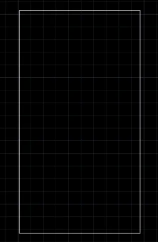
- Enter REC in command box
- Enter 12000 as length
- Enter 20000 as width
STEP 2:
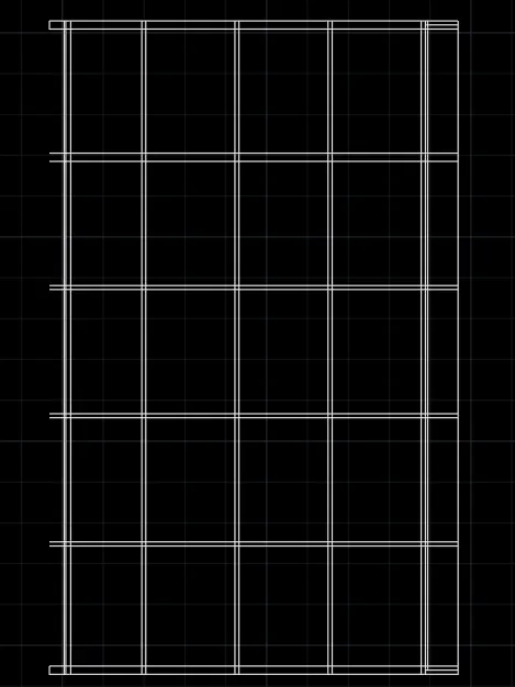
- Enter O in command box
- Enter 50 as offset distance and place it inside of upper and lower part
- Enter O in command box
- Enter 200 as offset distance and place it inside of upper and lower part
- Enter O in command box
- Enter 3800 as offset distance and place it at four places
- Enter O in command box
- Enter 250 as offset distance and place it below first 3800
- Enter O in command box
- Enter 125 as offset distance and place it at other 3800
- Enter O in command box
- Enter 200 as offset distance and place it inside of left part
- Enter O in command box
- Enter 2450 as offset distance and place it
- Enter O in command box
- Enter 2850 as offset distance and place it thrice
- Enter O in command box
- Enter 75 as offset distance and place it
- Enter O in command box
- Enter 125 as offset distance and place it inside of upper and lower part
- Enter TR in command box
- Delete all the unwanted lines
STEP 3:
- Enter L in command box
- Enter 350 horizontally and 250 vertically on one wall
- Enter CO in command box
- Copy the columns on other walls
- Enter O in command box
- Enter 125 as offset distance and place it above 1000 mm line
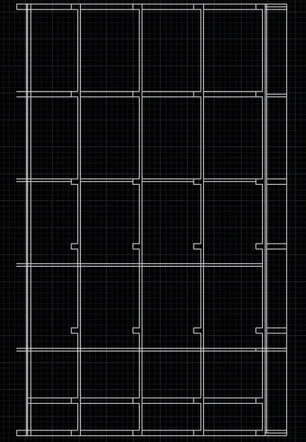
STEP 4:
- Enter L in command box
- Enter 200 as first point
- Enter 250 as next point
- Enter O in command box
- Enter 100 as offset distance and place it
- Enter O in command box
- Enter 1200 as offset distance and place it
- Enter L in command box
- Enter 100 as first point
- Enter O in command box
- Enter 50 as offset distance and place it
- Switch off ORTHOMODE
- Enter L and type 300
- Enter 100 as next point and enter 200
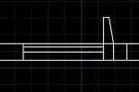
STEP 5:
- Enter CO in command box
- Copy the window
- Place it at 2700mm and 5700 mm distance

STEP 6:
- Enter REC in command box
- Enter 1000 as length
- Enter 1500 as width
- Place it at the centre of the room
- Enter CO in command box
- Copy the rectangle and place it at required rooms
- Enter REC in command box
- Enter 1040 as first corner point
- Enter 1800 as second corner point
- Enter 500 as length
- Enter 500 as width
- Place it at the centre of the room
- Enter CO in command box
- Copy the square and place it at required rooms
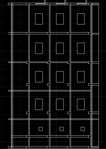
STEP 7:
- Enter O in command box
- Enter 500 as offset distance and place it
- Enter O in command box
- Enter 200 as offset distance and place it
- Enter L in command box
- Connect the middle line to the wall
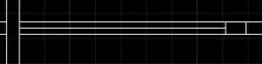
STEP 8:
- Enter CO in command box
- Copy the object
- Place it at 500 mm and 200 mm distance from the wall at two locations

STEP 9:
- Enter L in command box
- Enter 300 as first point
- Enter 250 as next point
- Enter O in command box
- Enter 100 as offset distance and place it
- Extend the outside
- Switch off ORTHOMODE
- Connect it to the wall
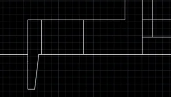
STEP 10:
- Enter L in command box
- Enter 200 as first point
- Enter 125 as next point
- Enter L in command box
- Enter 50 as first point
- Enter 500 as next point
- Close it
- Enter L in command box
- Enter 20 as first point
- Enter 5 as next point
- Enter ARC in command box
- Create two arcs and close it with the line
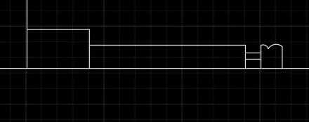
STEP 11:
- Enter CO in command box
- Copy those two objects
- Place it at three locations

STEP 12:
- Enter O in command box
- Enter 700 as offset distance and place it
- Enter O in command box
- Enter 100 as offset distance and place it
- Enter O in command box
- Enter 30 as offset distance and place it
- Enter O in command box
- Enter 1595 as offset distance and place it
- Enter O in command box
- Enter 70 as offset distance and place it
- Enter O in command box
- Enter 45 as offset distance and place it
- Enter O in command box
- Enter 60 as offset distance and place it
- Enter O in command box
- Enter 20 as offset distance and place it
- Enter O in command box
- Enter 10 as offset distance and place it
- Enter O in command box
- Enter 320 as offset distance and place it at 3 locations
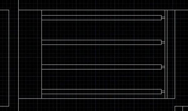
STEP 13:
- Enter CO in command box
- Copy the object
- Place it at 700 mm distance from the walls at two locations
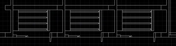
STEP 14:
- Enter L in command box
- Click the middle line
- Connect it with the wall
- Enter CO in command box
- Copy it and place it at two locations

STEP 15:
- Enter O in command box
- Enter 200 as offset distance
- Place it in 50 mm line at the left part
STEP 16:
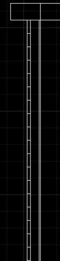
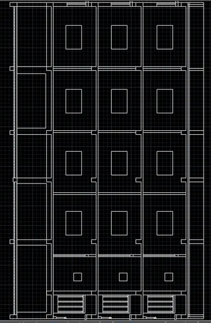
- Connect the columns with straight vertical line
- Enter O in command box
- Enter 350 as offset distance
- Place it at appropriate distance
- Enter TR in command box
- Delete the unwanted lines
STEP 17:
- Switch off ORTHOMODE
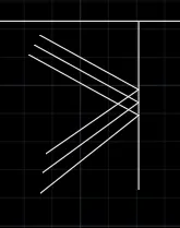
- Enter L in command box
- Enter 500 as first point
- Copy it at 20 mm distance twice
- Enter MI in command box
- Mirror those three lines
STEP 18:
- Enter DIMS in command box
- Click MODIFY. In SYMBOLS and ARROWS, Enter ARROW SIZE as 200.
- In TEXT, Enter TEXT HEIGHT as 200.
- In PRIMARY UNITS, Click DECIMAL in UNIT FORMAT, 0 in PRECISION.
- In LINES, Enter 10 as EXTEND BEYOND LINES and 20 as OFFSET FROM ORIGIN. Click OK.
- Click SET CURRENT. Click CLOSE.
- Click DIMENSIONS AND TEXT dropdown in LAYER.
- Enter DIML in command box and drag the dimensions.
- Enter DT in command box. Enter 200 as TEXT HEIGHT and 0 as TEXT ROTATION ANGE.
- Enter TEXT.
- Enter CO in command box. Copy the text and place it in another location.
- Enter TEXTEDIT in command box. Using this, editing in text can be done.
- Click the layers to give their properties in diagrams
- Save the drawing and rename it as AUTOCAD CHALLENGE 7
RESULT:
The Section-BB is created by lines using AutoCAD. The step-by-step procedure for creating section-BB is also explained. The Dimension is also entered in the diagram.