Creating a Layout, Section and Elevation with dimensions using AutoCad
Challenge 7: Creating the plan and sections as shown in figure by using proper dimensions techniques and dimensions styles to document the project.
- Residence Plan
Aim – To draw the residence plan by assuming proper dimensions using AutoCad software.
Procedure:
- First create a new Autocad file with metric units
- Type the command units and set it to decimal units and set it to millimeters
- Type the command Dimstyle and in the primary unit set the units to mm and precision to 0.
- Set the limits by using LIMITS command and specify the ends points.
- Give the Xline command and make a horizontal and vertical line
- From the vertical line give the offset of 250 mm in +x direction
- Again give the offset of 3100 mm in the same direction
- Again give the offset of 150 mm in the same direction
- Again give the offset of 2500 mm in the same direction
- Again give the offset of 75 mm in the same direction
- Again give the offset of 1250 mm in the same direction
- Again give the offset of 75 mm in the same direction
- Again give the offset of 75 mm in the same direction
- Again give the offset of 75 mm in the same direction
- Again give the offset of 1250 mm in the same direction
- Again give the offset of 150 mm in the same direction
- Again give the offset of 3000 mm in the same direction
- Again give the offset of 250 mm in the same direction
- Now from the horizontal line give the offset of 250 mm in –y direction
- Again give the offset of 2525 in the same direction
- Again give the offset of 3100 from the boundary line in same direction
- Again give the offset of 150 mm from last horizontal line in the same direction
- Again give the offset of 3225 mm from boundary line in the same direction
- Again give the offset of 150 mm from the last horizontal line
- Make the centre boundary line from the toilet D1 line.
- Trim the required line with the help of TRIM command
- Bed room, toilet 1&2, bed room 2 has been made.
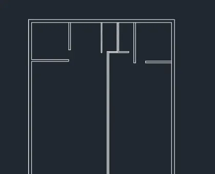
- From the inner boundary of the left corner bedroom give the offset of 3200 in –y direction
- From this line give the offset of 125 mm in both + y and –y direction
- From the 1st horizontal line at 3200 distance, give the offset of 250 mm in –y direction again
- From the main vertical boundary give the offset of 3225 in +x direction
- Again give the offset of 150 mm in same direction
- Trim off the required line
- Bedroom 3 and drawing room space has been made
- From the inner boundary of right corner bedroom give the offset of 2950 mm in –y direction
- Shift the main 200 mm in –x direction from the bedroom corner with the help of line command and again make a boundary of 250mm vertical downward to 17000 mm
- From the last horizontal line at 2950 distance, give the offset of 50mm in –y direction
- Again give the offset of 50 mm in same direction
- Again give the offset of 50 mm in same direction
- From the last horizontal line give the offset of 3050 in –y direction
- From the main boundary line in right side give the offset of 3225 mm in –x direction
- Trim off the required lines
- Extend the line and main internal boundary till drawing room corner and make vertical line
- At required length (around 1000mm) from the lower right corner of bedroom 3 make a vertical line 2400 in –y direction
- From this vertical line give the offset of 250 mm in +x direction
- Again give the offset of 1200 in same direction
- Now give the multiple offset of 250 mm in the same direction for getting stairs
- From the corners of the stairs make a line till the main boundary
- Trim the upper boundary for getting the open space
- From this last horizontal line give the offset of 250 mm in –y direction
- Again give the offset of 2550 mm in the same direction
- Again give the offset of 75 mm in the same direction
- Again give the offset of 1225 mm in the same direction
- Again give the offset of 2888 mm in the same direction
- Again give the offset of 250 mm in the same direction
- Now from the vertical main boundary give the offset of 3300 in +x direction
- Again give the offset of 150 mm in the same direction
- From the drawing room near stairs in D section extend the inner main boundary line till veranda
- Trim off the required line
- From the last bedroom made, from the horizontal line, give the offset of 3000 in –y direction and again give the offset of 250 mm in the same direction
- Now from the bedroom which is not in front of stairs, from the lower horizontal boundary give the offset of 3100 mm in x direction
- Trim the required line and the bedroom is made
- From the upper horizontal boundary of bedroom give the offset of 2150 mm in –y direction and again give the offset of 250 mm.
- Trim off the required lines
- From this boundary give the offset of 1150 in –y direction
- From main boundary line give the offset of 1375 in –x direction for making balcony
- Trim off the required lines
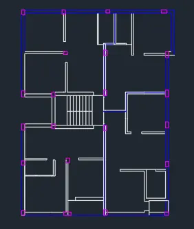
- Make the windows with the help of line command and offset command
- Make the columns with the help of rectangle command REC, of required size
- Make a ISO dash Line with the help of layer properties
- Write the text using the single line text
- Trim the required lines for doors
- Use the layer properties for showing different objects
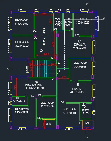
- Do the dimensioning using the DIMLINEAR
- Floor plan is made
Result: 1st ,2nd & 3rd floor plan is drawn.
Challenge 7: Creating the plan and sections as shown in figure by using proper dimensions techniques and dimensions styles to document the project.
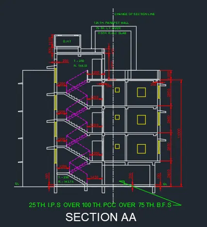
- Section AA
Procedure:
- First create a new Autocad file with metric units
- Type the command units and set it to decimal units and set it to millimeters
- Type the command Dimstyle and in the primary unit set the units to mm and precision to 0.
- Set the limits by using LIMITS command and specify the ends points.
- Give the Xline command and make a horizontal and vertical line
- From the vertical line give the offset of 250 mm in +x direction and 2000 mm in –ve x direction
- Again give the offset of 4400 and 250 mm in the same direction
- Now from the horizontal X line, give the offset of 150 mm in +y direction from the last vertical line
- Again give the offset of 500 mm in +x direction
- Now give the offset of 2450 in +y direction from last horizontal line
- Now from making stairs give the offset of 1450 in –x direction from the vertical column line
- Extend the line in downward direction for showing column foundation and do for all others column also
- From the floor level give the vertical line of 143.75 in +y direction and 250 in –x direction with the help of LINE command by repeating above procedure
- Join the line to the main boundary from last tread surface or from slab
- Make a inclined line by line command keeping the ortho off
- Now making the upper stairs portion use the mirror command and select the centre line. Make a stairs using the mirror command
- Do this repeatedly for no. of floor stairs
- Use the ISO dash line for showing the railing and up going stairs from left to right.
- Now from the stairs vertical railing handle give the offset of 1200 in +x direction
- Now again give the no. of offset of 50mm in the same direction
- Now again give the offset 1750 mm in the same direction
- Now again give the offset 150 mm in the same direction
- Now again give the offset 3000 mm in the same direction
- Now again give the offset 250 mm in the same direction
- Now from the first floor give the offset of 150 mm in the +y direction
- Then give the offset 2850 in the same direction
- Repeat these steps for the other two floors by giving the same offset
- Trim off the required lines for getting exact geometry
- From the last horizontal line give the offset of 50mm , 1000 mm and 2500 in the same direction
- Again give the offset of 450 mm in the same direction
- Join the required lines and now trim off the unwanted lines
- Make the required columns at floors using the LINE command
- From the horizontal last line having the 540 mm offset, give the offset of 1200 in +y direction
- And from the left boundary give the vertical offset at desired distance in +x direction
- Join the lines and make the inner rectangle of O.H.T with the help of offset command
- Trim off the unwanted lines
- Use the leader for showing the information of parapet wall and R.C.C slab
- Make the windows and windows lintel with the help of line command
- Use the layer properties for showing the different parts
- Use the single line text for providing details
- Do the dimensioning as required.
Result: Section AA is drawn as per given in the geometery.
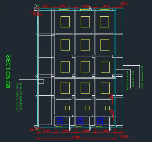
- Section BB
Procedure:
- First create a new Autocad file with metric units
- Type the command units and set it to decimal units and set it to millimeters
- Type the command Dimstyle and in the primary unit set the units to mm and precision to 0.
- Set the limits by using LIMITS command and specify the ends points.
- Give the Xline command and make a horizontal and vertical line
- From the vertical Xline give the offset of 150 mm in +x direction and 50 mm offset in –x direction
- Make the column foundation with the help of line command
- Now from the horizontal Xline give the offset of 250 m in +y direction
- Now from the last vertical line give the offset of 250 mm in –x direction
- Now again from this line give the offset of 250 mm in –y direction
- Now again give the offset of 2850 mm from 2450 mm line in +x direction
- Now again give the offset of 2850 mm from 2450 mm line in +x direction
- Now again give the offset of 2850 mm from 2450 mm line in +x direction
- Now again give the offset of 1000 mm from 2450 mm line in +x direction
- Now from the lower horizontal 250 mm thickness give the offset 1150 in +y direction
- Again give the offset of 250 mm in same direction
- Again give the offset of 2150 mm in same direction
- Again give the offset of 150mm in same direction
- Again give the offset of 2863 mm in same direction
- Again give the offset of 150mm in same direction
- Again give the offset of 3050 mm in same direction
- Again give the offset of 150mm in same direction
- Again give the offset of 2950 mm in same direction
- Again give the offset of 150mm in same direction
- Again give the offset of 3225 mm in same direction
- Again give the offset of 250 mm in same direction
- Now from 150 mm boundary thickness make the no. of columns at required points by giving desired lengths with the help of line command
- Make the small and large window with the help of rectangle command
- Make the balcony with the help of LINE command from the 250 mm thickness boundary.
- Use the leader for showing the information of parapet wall and R.C.C slab
- Make the windows and windows lintel with the help of line command
- Use the layer properties for showing the different parts
- Use the single line text for providing details
- Do the dimensioning as required.
- Section BB is made.
Result: Section BB is drawn as per given in the geometry.