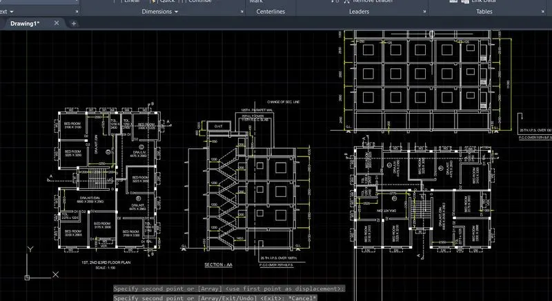
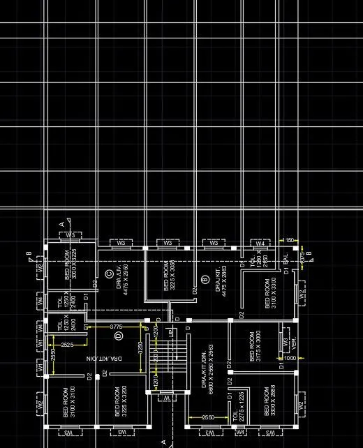
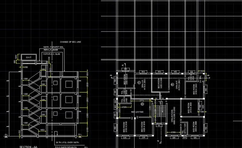
Creating a Layout, Section and Elevation with dimensions using AutoCad
AIM
To draw the PLAN and SECTIONS using the various commands in Auto CAD.
PROCEDURE
- To create a new drawing sheet .
- Type ,,UN’ to set the units of current format of measure.
- Type ,,LIMITS’ to set the maximum dimension limits on the particular page.
- Type ,,L’ - Line commands allows to creating a line where the end points allows creating a line where the end points are dimensional co-ordinates.
- TYPE ,, XLINE’ to draw the infinity length of line, can be draw it free or set it to be Horizontal or Vertical, follow a certain angle.
- Type ,, OFF’ – offset command to create a new object that specified distance from an existing objects or through a specified points. ( For EX .. Rows and Column of the table.
- Type ,, Tr’ – Trim command is used to trims off an objects cutting the extra edges on objects.
- Assumed the size of the Doors and Windows as per construction standard.
- Wall Thickness of Exterior id 250mm and Interior is 150mm.
- Type ,, Text’ to create the text ( SINGLE or MULTI ), select and change the properties of standard size.
- COPY – this commands is used to selected objects from a given square to destination, learning a copy at the originally selected location.
- ROTATE – rotate the objects around a specified point.
- MOVE – moves the objects to the destination place from the source place.
- After drawn the plan, to take the section of AA and BB.
- Then, to draw the taken section of Cross section diagram.
- TYPE ,,DLI’ in command bar to give the dimension of the plan.
- TYPE ,,D’ in command bar to give the size of the dimension and size of the arrows, changing tool command is DDIM.
- Type ,, Leader’ or from annotative to draw the leader line.
- Finally, to save the diagram.
RESULTS
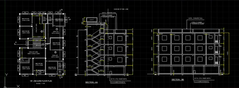
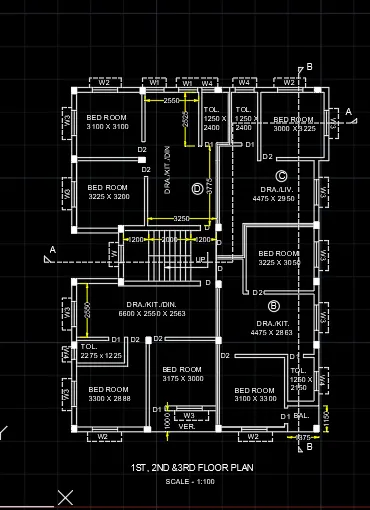
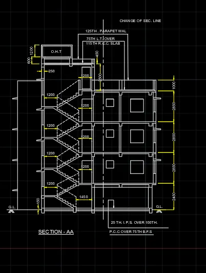
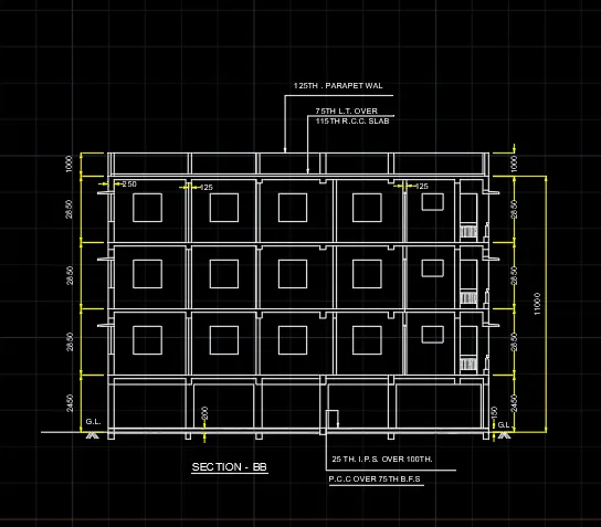
The diagram of the given Plan, Section-AA, section-BB is drawn as per dimensions using the software of Auto.
DIAGRAM