Creating a Layout, Section and Elevation with dimensions using AutoCad
Week 7-Assignment 7-Module 2
Aim: To plot the Floor Plan and Sections using the proper dimension techniques and dimension styles to document the project.
Introduction:
- Plan, Section and Elevation are different type or view of drawings used in Construction Industry to graphically represent a building design and construction.
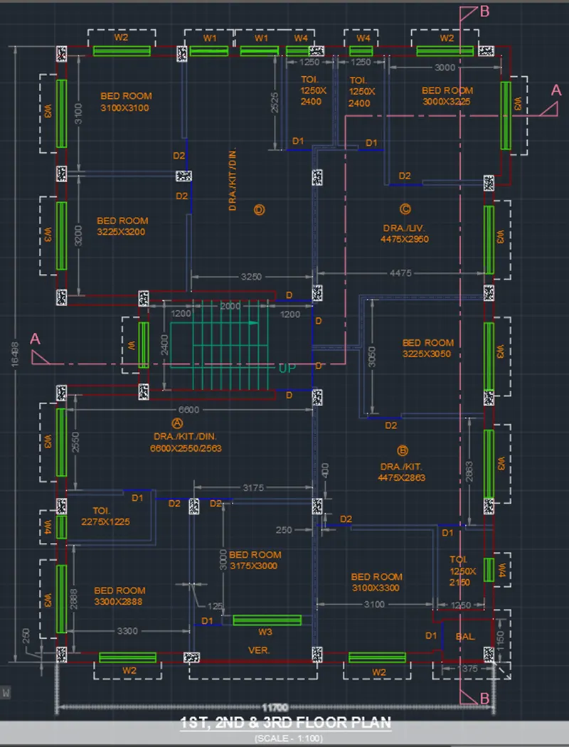
- Plan Drawing is drawn from a horizontal plane looking down from above. This is as if you sliced through a space horizontally and stood overlooking down on it.
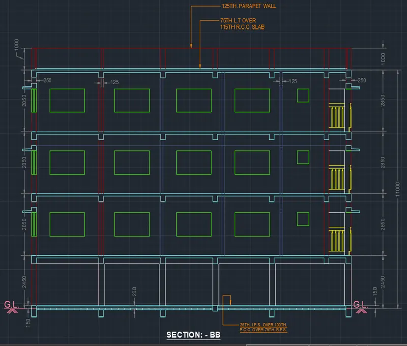
- Section Drawing is drawn from a vertical plane slicing through a building. This is as if you cut through a space vertically and stood directly in front looking straight at it.
- Elevation Drawing is drawn from a vertical plane looking straight on to a building facade or interior surface. This is as if you directly in front of a building and looked straight at it.
Procedure:
A. Starting AutoCAD;
- Search for the AutoCAD icon from your desktop and double click it to make it run or you may search it from windows search tool and open from there if no shortcut in the desktop.
- You may simply click the “Get Started-Start Drawing” icon once the AutoCAD is opened or you may click the Application Menu tab with the “A” AutoCAD logo on the top -left most side of the screen and select new. From the new you may find a variety of templates that suits your requirements.
- For this exercise, we will just simply proceed on Get Started-Start Drawing” icon and set up the measurement units inline with the drawing requirements.
B. Setting the Drawing Parameters;
- Set up the measurement units according to sketched information provided.
- To set up that, a much faster way is to type “units” in the command line and hit enter or space bar. The Drawing Units Dialog box will then pop up and measurement parameters will then set up in line with the requirements. Similar thing, you need to set up the dimension through the DDIM command.
- As for the gridlines, you may right click gridline icon in the status bar and go for the drafting settings. Under the Snap and Grid of the Drafting Settings Dialog box, you may set up the needed spacing of grids along its X and Y axis. “DS” command will also work to pop up the Drafting Settings Dialog box.
C. Starting the exercise;
- Combination and manipulation of all the different coordinate entry methods, drawing and modifying tools learned from weeks 1 to 7 were being used here in the completion of all the exercises given and result as pasted below.
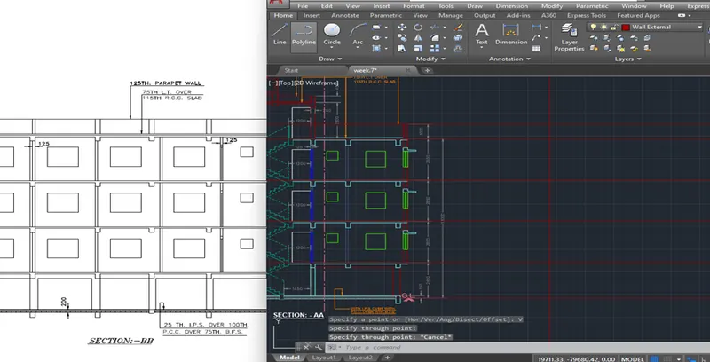
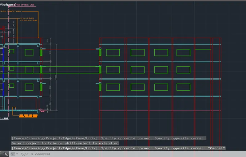
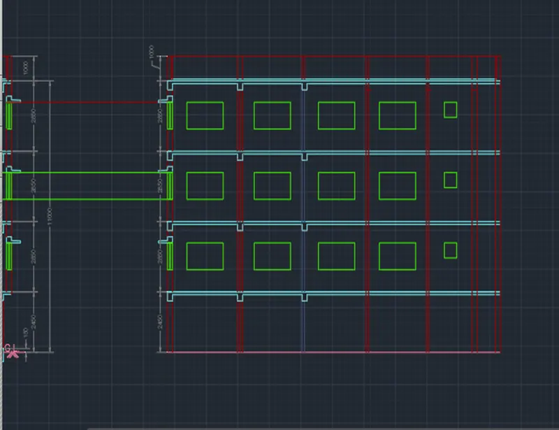
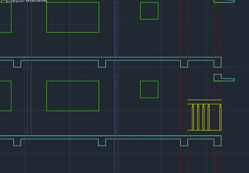
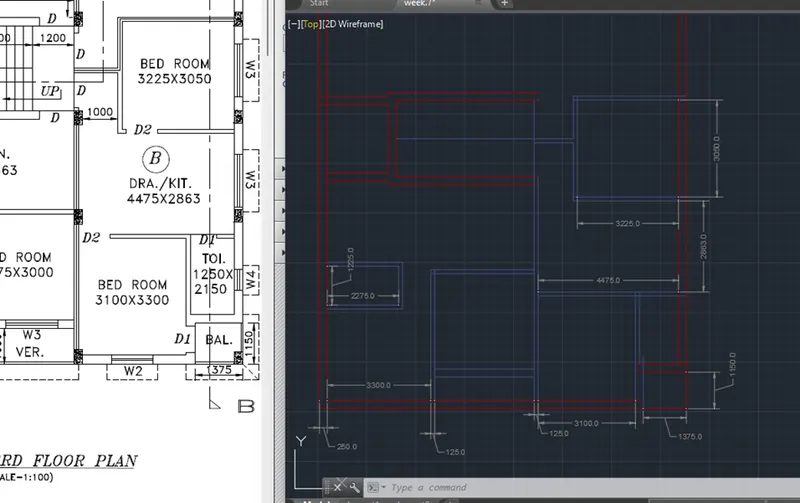
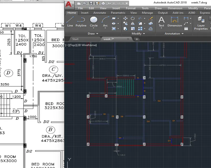
- I have attached some screenshots while plotting the needed five exercises to show the procedure on how it was done to come out with the requested layouts.
D. Challenge;
- In general, below commands/functions were being used while working on the exercises.
- Units
- LIMITS
- DDIM
- XLINE
- LINE
- PLINE
- OFFSET
- DIVIDE
- PTYPE
- MIRROR (MI)
- CIRCLE
- FILLET
- MTEXT
- DTEXT
- MLEADER
- DIM
- DIMCONTINUE
- Manipulation with Ortho mode and Object Snaps
- LAYERS
- UTILITIES
- MATCHPROP
- ANNOTATION
- PDF IMPORT
- RAY
- DIMBREAK
- COPY
- HATCH
- SCALE
- BLOCK
- Assumptions:
- Window Sizes;
W1= 1000 X 1100
W2= 1085X 1085
W3= 1800X 1085
W4= 610 X 610
W= 1200X 1100
- Door Sizes;
D= 1200 X 2100
D1= 750X 2100
D2= 900 X 2100
- Column = 400x250
Challenge 1: Steps:
- Set up the Units, Limits and Layers.
- Draw the Construction Line using XLINE, start from the bottom left.
- Construct the room-by-room partitions using the commands; offset, trim, fillet and erase as applicable while maintaining proper layering.
- Use the dimension given from the sketch provided and only assumptions on windows, doors, and columns.
- You may plot the walls, columns, followed by doors, staircase and windows.
- Its best to use Block for Windows and Doors as grouped for accuracy and speed.
- Annotations to follow.

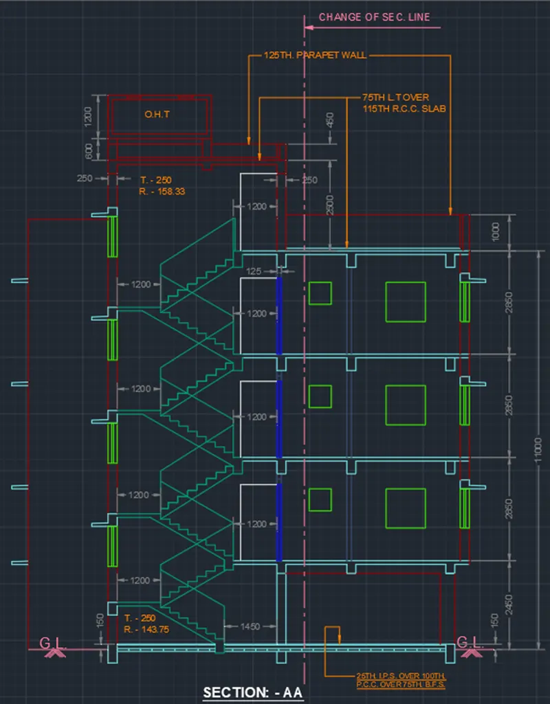
Challenge 2: Steps:
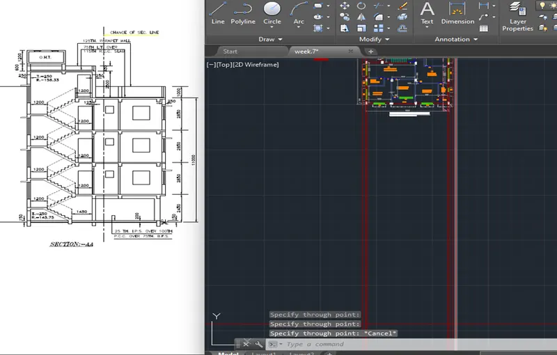
- Use your Challenge One output as a basis of your drawing using orthographic projections technique.
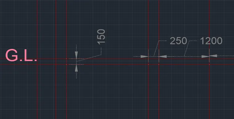
- Draw the Construction Line using XLINE for horizontal since most of the vertical ones will be from the plan projections. Start from the bottom left.
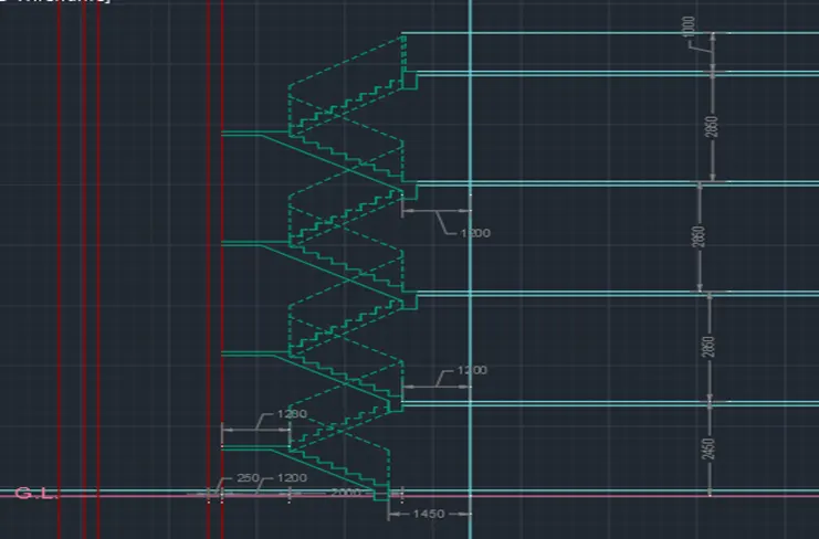
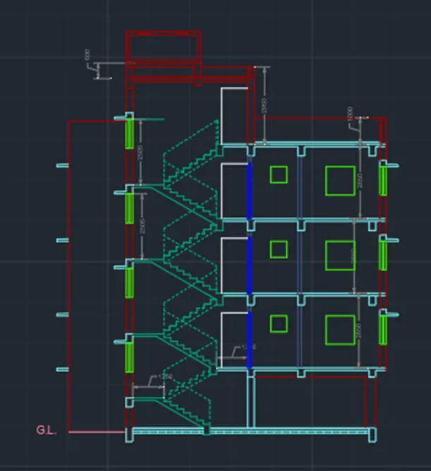
- Plot the level-by-level partitions using the commands; offset, trim, fillet and erase as applicable while maintaining proper layering.
- Use the dimension given from the sketch provided and only assumptions on windows, doors, and columns.
- You may plot the columns, walls, slabs, followed by staircase, windows and doors.
- Annotations to follow.
Challenge 3: Steps:
- Use your Challenge One and Two output as a basis of your drawing using orthographic projections technique as applicable.
- Draw the Construction Line using XLINE for horizontal and Vertical Projections. Start from the bottom left.
- Plot the level-by-level partitions using the commands; offset, trim, fillet and erase as applicable while maintaining proper layering.
- Use the dimension given from the sketch provided and only assumptions on windows, doors, and columns.
- You may plot the columns, walls, slabs, followed by windows, terrace and further slab finishes for GF and Roof Top.
- Annotations to follow.