Creating a Layout, Section and Elevation with dimensions using AutoCad
AIM: Create the Plan and Sections as shown in the Figures. Use proper dimension techniques and dimension styles to document the project. Assume the sizes of the doors and windows as per construction standards.
INTRODUCTION:
- Here i have used inner/outer wall dimensions of 5"/10".
- Doors are classed into types as D1/D2 of dimension 750/1000mm.
- Always specify the units with precision requirement before sketching the drawing.
- Assign the origin before proceeding for sketching.
- Here I have given the properties as given below:
Dimension lines: red colour
Extension lines from dim lines: 230
offset from the object: 255
TEXT height/style: 250/ARIAL
Arrows & Symbols: 5, datum filled triangle on both sides
PROCEDURE:
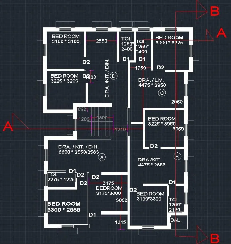
FIGURE (a):
- Use line command nested within tra command.
- It's better to start the drawing from the outer side to inner side to minimise the chances of errors.
- Staircase section should be drawn at different position from the sketch followed by using MOVE command to minimise the chances of error.
- It’s better to draw the Grid Lines right angle to each other before sketching.
- Labelling & texting at the commencement of sketching helps in minimising the human error.
- After sketching the drawing, Hatching should be done for aesthetic as well as for better understanding at the Walls, column cross-section.
- After Hatching, labelling & texting should be done for making this nectar to the reader.
8. It’s better to freeze the layer of dimensioning done for the Grid lines
FIGURE(b):
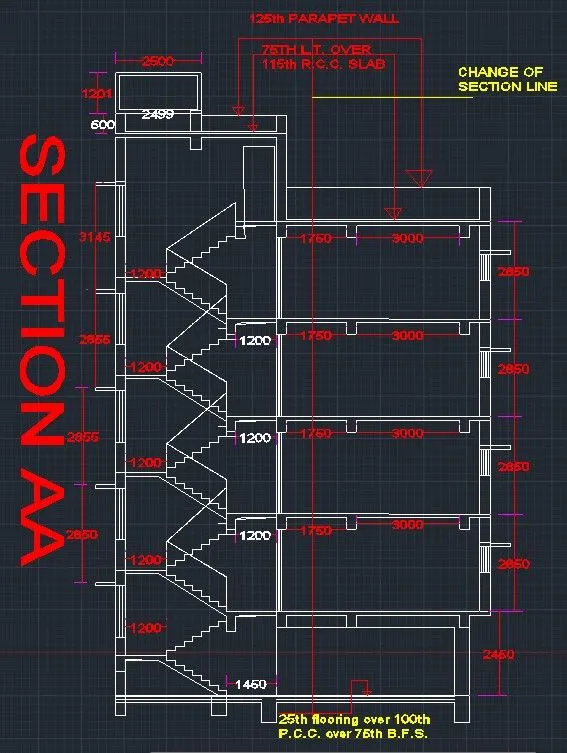
- Figure (b) is drawn keeping in mind red line(A-A) passing through plan view.
- It's much accurate to use ray command at the section where the section line is crossing the interfaces.
- After raying, all the vertices shall be joined using line command to draw the floor level at different elevation.
- After joining all the corners, TRIM all the extending lines out from the section elevation plan.
- it's better to draw the staircase section at different place & then relocate the section at suitable location using move command.
- As this drawing has lot of symmetry as well as similar sections locating in a range line, CO command will help a lot in minimising error along with excellent precision.
- Windows depicted in the below figure are located at 750mm from the top flooring of the staircase landing at each floor.
- After sketching, Labelling & texting should be done preceding Setting option at annotate command whose information is already shared at the introductory part.
FIGURE(C):
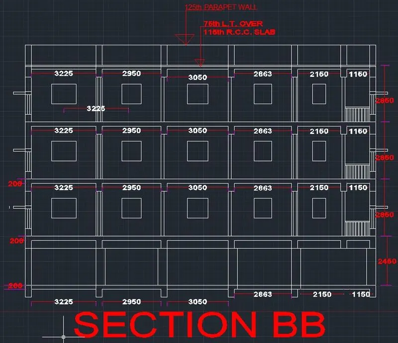
- Role of Ray lines in elevation drawing is analogous to Grid lines in floor plan view.
- set the floor plan view in front, Use Ray command to draw the lines cutting by the section line B-B at the intersections.
- Use Line command to join the ray vertices.
- After all, debug the drawing section using the TR command.
- Windows in the above snapshot is traced out at a tracing distance (1000, -750) from the top left corner of every bay at each floor.
- As the drawing has a lot of symmetry in their plane, so it’s better to use CO command to minimise the chances of error.
- labelling & texting should be done, before forgetting to set the properties using annotate command in the drawing.
- window canopy has a projection of 600mm.
- Ground beam section has dimension of 300*600 mm.
- Balcony grilling are spaced at 150 mm with steel pipe thickness of 50mm.
- Inner/outer wall thickness is of dimensions 150/300 mm.
- Floor slab comprises of 75mm covering over 125 mm R.C.C slab making a thicness of 200mm.
RESULT:
here i have first drawn the Drawing in the AUTOCAD software followed by taking the screenshots and then pasted it here in the form of screenshots.