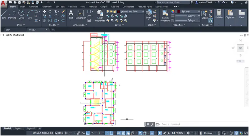
Creating a Layout, Section and Elevation with dimensions using AutoCad
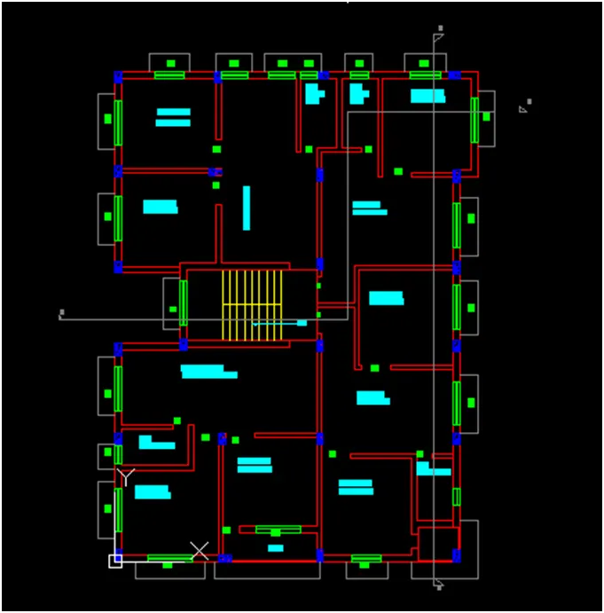
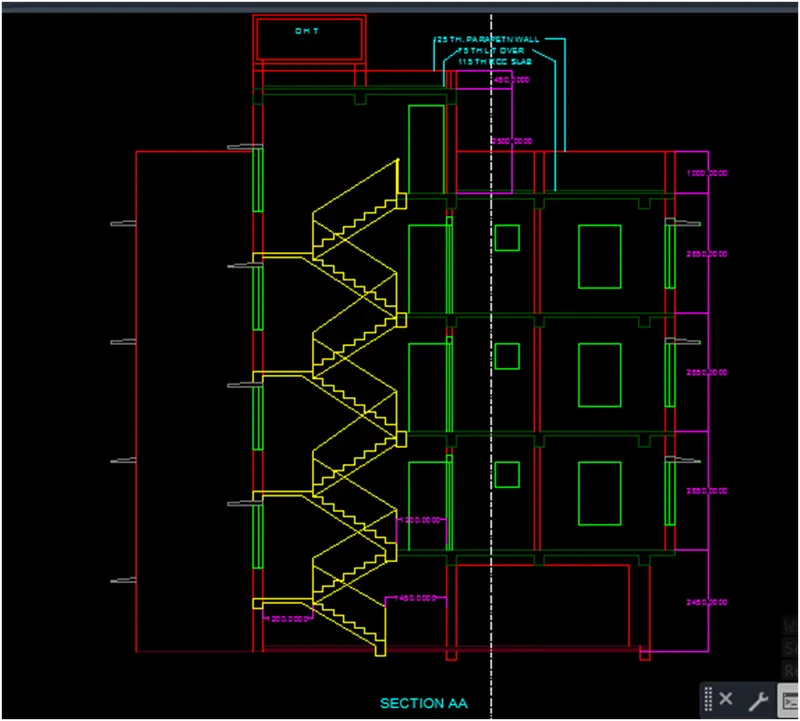
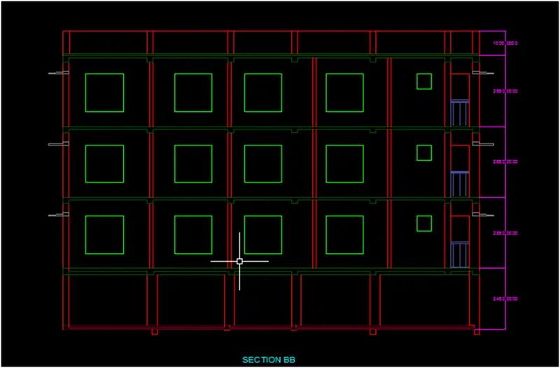
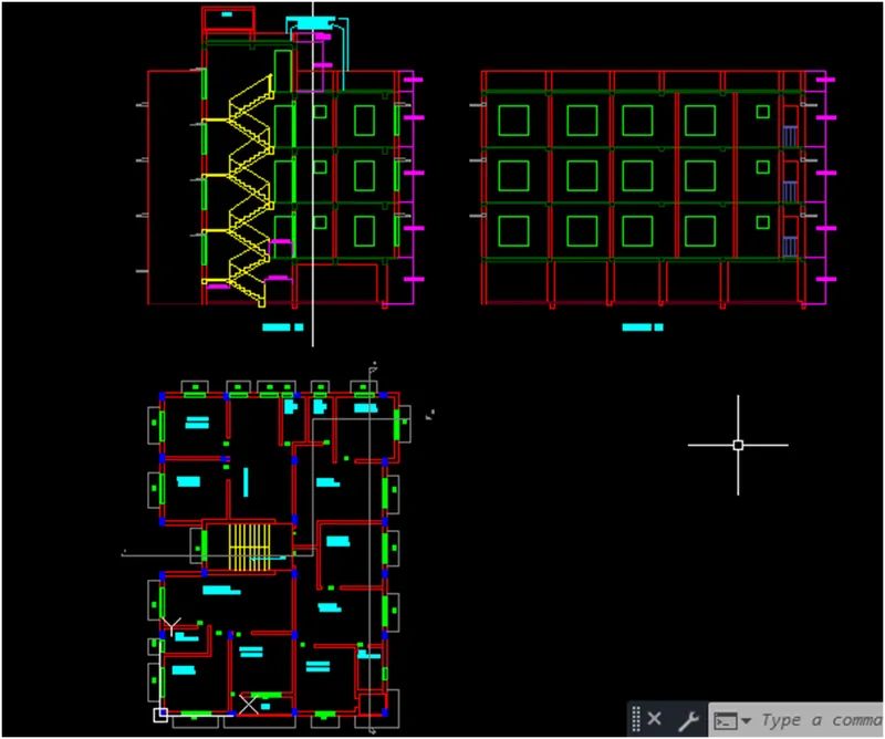
Q.Create the Plan and Sections as shown in the Figures. Use proper dimension techniques and dimension styles to document the project. Assume the sizes of the doors and windows as per construction standards. Refer to sections for stair details if required.
Ans:
Aim: To draw the PLAN, SECTION, ELEVATION of a building as shown in the diagram using AutoCAD software
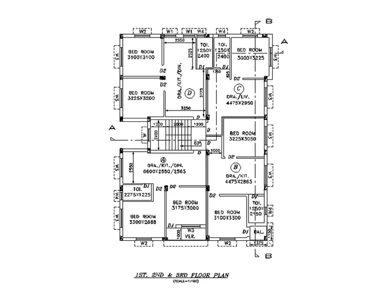
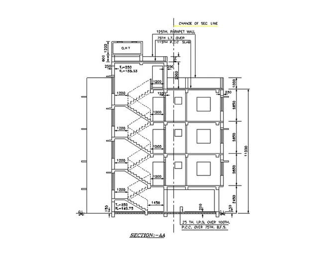
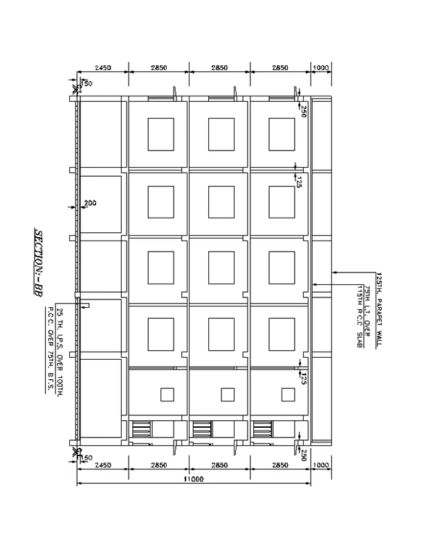
Procedure:
Step 1 Basic settings
- Open AutoCAD
- Open new drawing
- Set units (measurements as decimal, precision to 0.0 , angle as decimal degree)
- Enable Ortho mode on
Step 2
- Enter command dimstyle and click on modify
- Set unit to decimal and precision to 0.0
Step 3: outline
- Use X-line by typing “XL” in command box
- Select vertical and plot a line by using cursor
- Use X-line by typing “XL” in command box
- Select horizontal and plot a line by using cursor
Step 4: drawing of plan
- Use “xline” command and draw vertical and horizontal construction lines
- Use “o” command to create offset lines by providing sufficient lengths
- Use “line” tool to draw the lines at required places
- Turn on the object snap to locate mid and end points easily
- Use “trim” tool to erase the unwanted portion of lines
- Use “c” in command box to create circles at any place
- Use chamfer tool and select angle and give value to provide curve edjes
- Draw doors and windows of different lengths as given in diagram
- By using different tools like (mirror , rotate , copy) create more number as required
- Use “move” tool to move the item to a particular place
- Select line tool and draw the section AA and BB lines as given in the diagram
Step 5: layers
- Go to layer properties from home ribbon
- Now select new layer
- Rename it as outline and assign colour
- Do the same for diff layers and assign diff colors
- Press enter and close
- Now select the lines and assign the layers from layer panel in home ribbon
Step 6 : Drawing of section and elevation
- Use “X line” command to project the walls , columns and other wanted information from PLAN to section
- Use “o” command to create offset lines by providing sufficient lengths
- Use “line” tool to draw the lines at required places
- Use “trim” tool to erase the unwanted portion of lines
- Use “c” in command box to create circles at any place
- Use chamfer tool and select angle and give value to provide curve edjes
- Draw doors and windows of different lengths as given in diagram
- By using different tools like (mirror , rotate , copy) create more number as required
- Use “move” tool to move the item to a particular place
Step 7: dimension
- Select dimensions tool from ribbon
- And give the all dimensions as given in diagram
Step 8: text
- Select text tool by typing text in command box
- Click the cursor at required points
- Give the text as shown in figure
- Can change the height of text by right click on the text given and properties tab
RESULT: The PLAN, SECTION, ELEVATION of a building are drawn and all the dimensions are given as shown in the diagram using AutoCAD software