Creating a Layout, Section and Elevation with dimensions using AutoCad
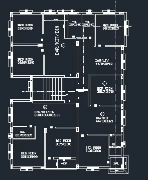
Aim: To create the Plan and Sections
Introduction: To create the Plan and Sections by using autocad
Procedure:
Step1:
- Frist set the units by typing “UN” in the command
- Set the units in the metric format
- Next set the limits as per the required of plan
Step2:
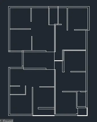
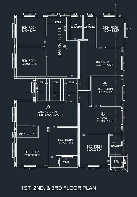
- Creation of external and internal walls of the given plan
- Now take the command “XL” for the construction line V for the vertical line and H for the horizontal line
- Now next take the offset command and make the 230mm offset for all the external walls and 115mm for all the internal walls
- Now take dimension refrance from the given plan
Step3:
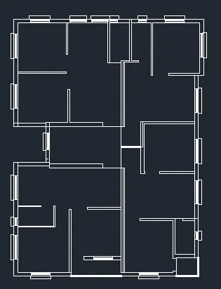
- Creating and placing of windows
- W1=(800mm), w2=(1000mm)
- W3=(1200mm), w4(500mm)
- First create a window make it as a block by using the command B select the pick point then select the object give the names of the block
- Next select the rotated, copy, and move as per required of placing the object
Step4:
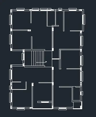
- Creating and placing of columns
- Assume all the columns are 9”x18” (230x460mm)
- Frist take the rectangle “REC” @230x460
- Rotated the columns as per need of structure
- Take the hatch command and mark the hatch in the columns
- Creating of stare case take the line command and mark the line from start point end of the wall and take the offset of 300mm for trade and 150mm for the riser
Step5:
- creation of text and dimensions
- take the command mtext select the base point write the text set the height of the text
- next copy the and place the text and then edit as per the required of the text
- next take the DIM for the dimensions and select the first point and second place the dimension
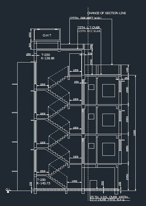
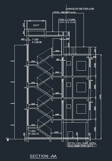
- section: A
step1:
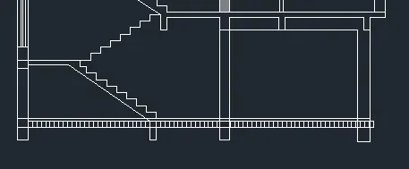
- Creation of section A first take a XL line for the refrance from the above plan mark the edge lines of the columns
- Now continue to XL line mark the ground level line then take the offset of 150mm and 200mm for the level from the base point
- Next take the offset of 2450mm from the base line for the height of the ground floor
- Take the oddest of 100mm for the thickness of the slab 300mm for the beam thickness from the ground floor and 250mm for the columns
- For the staircase first take the poyline select the base point draw the trade 230mm and riser as 150mm mid leading is 1200mm as per the given thickness of the waste slab is 100mm
Step2:
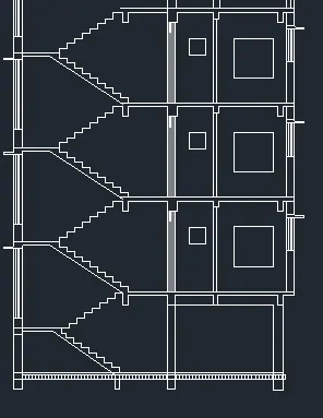
- Creation of first floor of the section-A columns and windows
- Frist take extend command by typing EX in the command box and extend the columns to the height of the 2850mm for the first floor and take the columns width as 250mm
- Now for the creation of windows take the line command check the size of the windows the size of the window1= 2100mm and the size of the window2 = 50mm
- Create the windows and make it as block select the base point and pickup and save it by giving name of the block
- Now take the window copy it and place it in the positions
- Copy the staircase from the below

Step3:
- For the creating of the 2nd and 3rd floor
- Take the copy command by typing CO in the command box
- Select the base point and copy it
Step4:
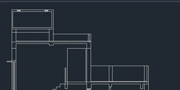
- Creation of roof of the plan
- First extent the height of the column to 2500mm as per given in the plan
- Now mark the 800mm height for the parapet wall
- Mark the 1200mm length for the O.H.T wall and take the offset of 100mm for slab
Step5:
- Creation of dimensions and text
- Take the command DIM for the dimensions select the first point and second point for the dimension and place it.
- For text type the mtext in command write the text then copy select the point place it were the text is required next give the height of the next edit wirete the text as per the requirement
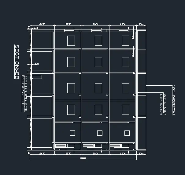
- Section: B
Step:1
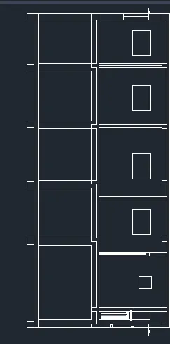
- Frist take a XL line for the refrance and mark a vertical line and horizontal line
- Next take the offset command and take the offset of 2450mm to vertical line form the refrance and create the columns and from the base line take the offset of 150mm for the foundation and 200mm for the plinth level from the ground level
- Now for the slab take the offset of 100mm and take the thickness of the columns as 250mm as per the given
- Now create the windows from the projection next take the copy command select the base point place above of each
Step2:
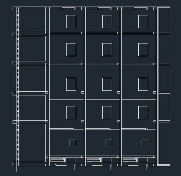
- Now the copy command and select the object to copy and select the pickup point and place it with the distance of 2850mm
Step3:
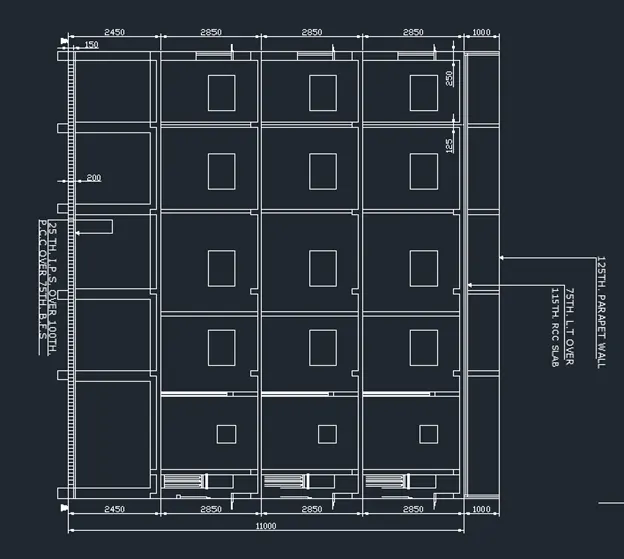
- Creation of dimensions and text
- Take the command DIM for the dimensions select the first point and second point for the dimension and place it.
- For text type the mtext in command write the text then copy select the point place it were the text is required next give the height of the next edit wirete the text as per the requirement
Result:
- 1st, 2nd, 3rd floor plan
2. Section: A
3. Section: B