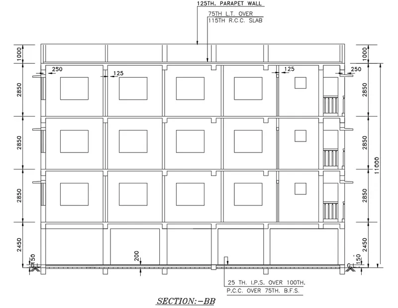
Creating a Layout, Section and Elevation with dimensions using AutoCad
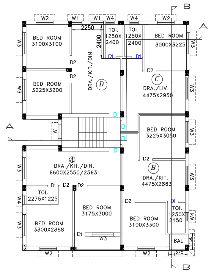
Aim: - To create the Plan and Sections as shown in the Figures above using AutoCAD.
Introduction: - The plan is the most important part of any building construction. It provides the top view of all the structural elements. The Plan detailed drawing is created in AutoCAD using primarily the Line tool and after sketching, the dimensions and text are provided with the use of layers. The procedure of drawing is explained in detail with diagrams of each step and the final result is given.
PROCEDURE: -
Before we start the drawings we need to set up the drawing as Metric and the units into Decimal Units.
Following are the steps in order to set up the drawing as Imperial Template and the units into Engineering Units.
- Go to Application Menu or click CTRL + N (New)
- Click on New from the Application Menu
- A popup menu appears, click on the first tab known as Start from Scratch > Select Metric
- Now click on the third tab known as Use a Wizard > Go to Advance setup > A Dialog box appears > Select the unit of measurement as Decimal > Press Next > select Angle as Decimal Degrees > Press Next > Select Angle Measure > Press Next > Select Angle Direction > Press Next > Select Area > Click Finish
- Set the page limit by entering Limits in the command tab. The lower left corner is specified as 0,0 and the upper right corner is specified as 410, 297.
- In the Drawing Units dialog box, select 'Engineering' in Type; ' 0 ' in Precision; and 'Millimeter' in Insertion scale.
- Click OK
- Now we are all set to go.
Now,
- Import the drawing pdf which we are given to draw.
- Go to Ribbon Tab
- Click on Insert
- Then click on the PDF Import tool
- Import the required pdf.
Now,
- In order draw the drawing perfectly according to the size, we need to Scale it.
- So draw any dimension of the imported drawing like the size of the section wardrobe and draw it on the workspace by using line tool and direct distance method.
In order to Scale the Drawing,
- First select the entire imported drawing
- Select the base point
- Go to Reference option in the command box
- Select any dimension length of the imported drawing
- Then directing enter the scale length like 2550 or
- You can click on Points in the command box and select the two points of the line i.e., the first and the end point of the line which you have drawn.
- Now you are all set to go.
Now,
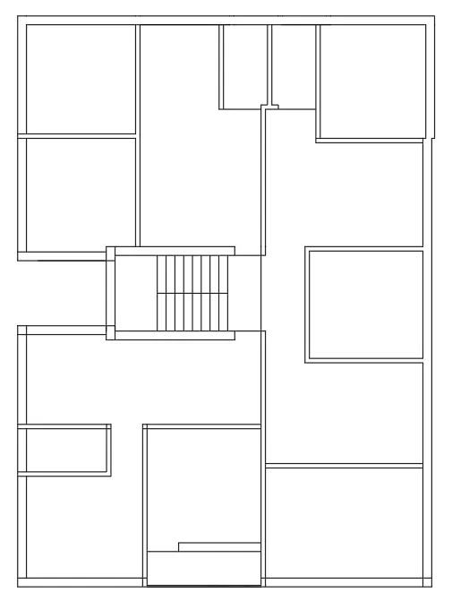
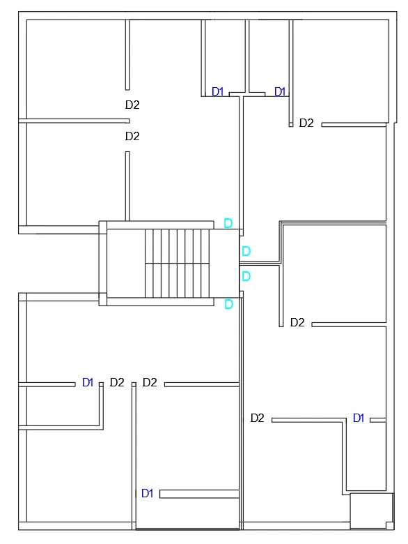
- Draw the External wall of the plan.
- The horizontal outer line is drawn to a distance of 11850 and take the external wall width as 250mm that is the wall thickness.
- Draw the Internal wall plan.
- The vertical outer line is drawn to a distance of 16138.
- Take the internal wall width as 125mm.
- Draw the stairs of tread 250mm and riser 150mm.
- Type 'O' or Offset in the command box.
- And enter a distance of 250mm and do a offset of 8 times.
Now,
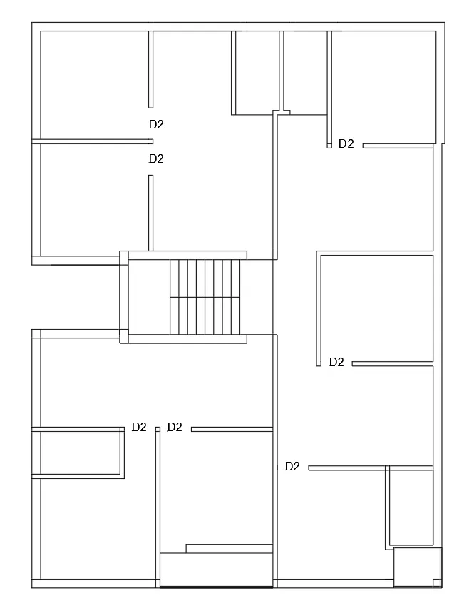
- Draw the doors D2 of size 900 X 2100.
Now,
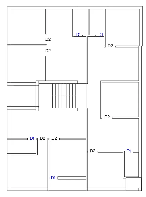
- Draw the doors D1 of size 750 X 2100.
Now,
- Draw the doors D1 of size 800 X 2100.
Now,
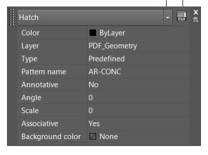
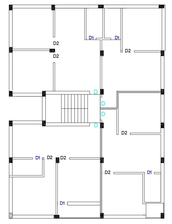
- Let us give the columns of size 400mm X 250mm
- Take the following Hatching.
So, we have the following columns,
Now,
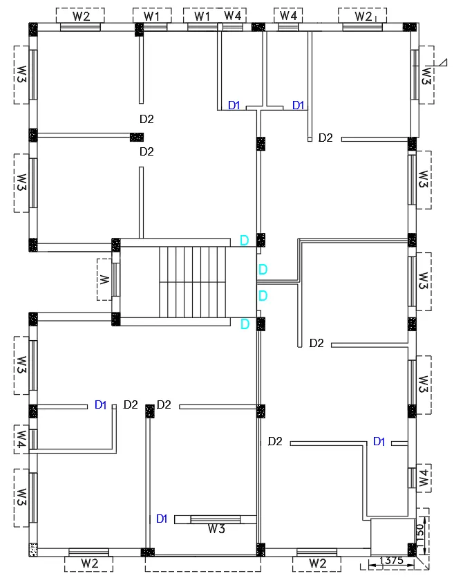
- Let us draw the various windows
- W1 = 900mm X 1200mm
- W2 = 1200mm X 1200mm
- W3 = 1500mm X 1200mm
- W4 = 600mm X 750mm
Now, its time for Dimension.
- Select the Layer pdf_text for the various dimension.
- Type 'D' or Dimension Style
- Select the size of the arrow as 250 and text height as 300.
RESULT: -
--------------------------------------------------------------------------------------------------------------------------------------------------
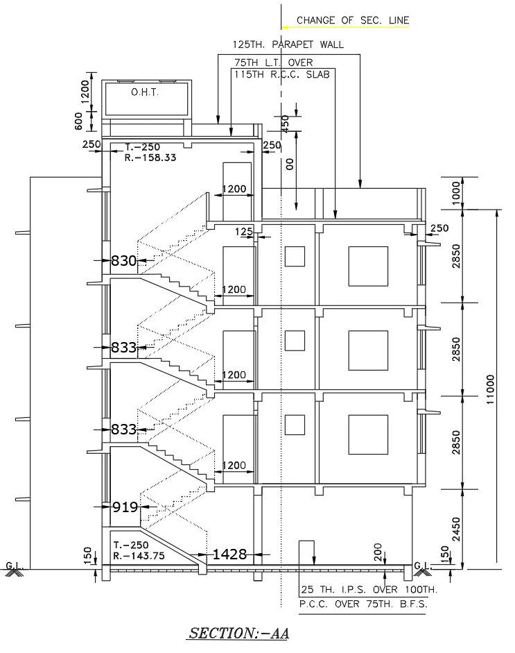
Aim: - To create the Section AA as shown in the Figure above using AutoCAD.
Introduction: - The plan is the most important part of any building construction. It provides the top view of all the structural elements. The Plan detailed drawing is created in AutoCAD using primarily the Line tool and after sketching, the dimensions and text are provided with the use of layers. The procedure of drawing is explained in detail with diagrams of each step and the final result is given.
PROCEDURE: -
Before we start the drawings we need to set up the drawing as Metric and the units into Decimal Units.
Following are the steps in order to set up the drawing as Imperial Template and the units into Engineering Units.
- Go to Application Menu or click CTRL + N (New)
- Click on New from the Application Menu
- A popup menu appears, click on the first tab known as Start from Scratch > Select Metric
- Now click on the third tab known as Use a Wizard > Go to Advance setup > A Dialog box appears > Select the unit of measurement as Decimal > Press Next > select Angle as Decimal Degrees > Press Next > Select Angle Measure > Press Next > Select Angle Direction > Press Next > Select Area > Click Finish
- Set the page limit by entering Limits in the command tab. The lower left corner is specified as 0,0 and the upper right corner is specified as 410, 297.
- In the Drawing Units dialog box, select 'Engineering' in Type; ' 0 ' in Precision; and 'Millimeter' in Insertion scale.
- Click OK
- Now we are all set to go.
Now,
- Import the drawing pdf which we are given to draw.
- Go to Ribbon Tab
- Click on Insert
- Then click on the PDF Import tool
- Import the required pdf.
Now,
- In order draw the drawing perfectly according to the size, we need to Scale it.
- So draw any dimension of the imported drawing like the size of the section wardrobe and draw it on the workspace by using line tool and direct distance method.
In order to Scale the Drawing,
- Firstly,
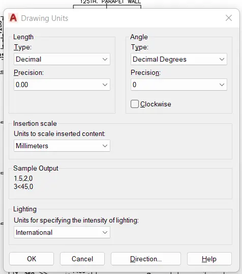
- Type UN or unit and then take the decimal precision upto 2 decimal points.
- Then
- Select the entire imported drawing
- Select the base point
- Go to Reference option in the command box
- Select any dimension length of the imported drawing
- Then directing enter the scale length like 2550 or
- You can click on Points in the command box and select the two points of the line i.e., the first and the end point of the line which you have drawn.
- Now you are all set to go.
Now,
- Type L or Line and draw a line of lrngth 9413 horizonatally.
- Type O or Offset in the command box and give a offset of 150mm in downward direction the above drawn line.
- Press Escape to close the command.
- Again type O or Offset in the command box and give a offset of 70mm in downward direction the above 150mm drawn line.
- Draw the column below groundlevel as shown in the figure. Take width 250mm and depth 489mm.
- Again type O or Offset in the command box and give a offset of 245mm in the 75mm thickness.
- Take the number of offsets as per requirement.
- Let us draw the stairs now.
- Take tread size as 250mm.
- Take riser size as 143.75mm.
- Take one flight length as 2040mm.
- Take Landing as 909mm.
- Type O or Offset in the command box and give a offset of 25mm in downward direction of the stair foundation.
- Now let us draw the first floor.
- Draw the beam of size 245 x 250mm.
- Draw a vertical line of 2551mm
- Draw horizonatl line of 1200mm
- Take offset of 122mm in downward direction.
- Draw the chajja of size 700 X 70 mm.
- Let us draw the first floor.
- Draw a vertical line of 2850mm.
- Rest do the same as done in the ground floor like the beams and the columns.
- Draw the first floor chajja of size 448 x 70mm.
- Draw the window of size 1188 x 900 mm
- Draw the door of size 988 X 2079 mm.
- Draw the first stairs taking Riser = 143.75mm and Tread = 250mm.
- Draw the second, third and the fourth floor in the same way as we drew the first floor.
- Draw the overhead tank.
- Draw two floating column of 600mm X 250mm.
- Now the draw the tank of 1200mm X 2627mm.
- Provide the two openings of the overhead tank.
- Draw the parapet wall of 1000mm height.
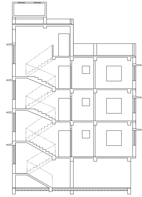
- So we have the following drawing.
Now, its time for Dimension.
- Select the Layer pdf_text for the various dimension.
- Type 'D' or Dimension Style
- Select the size of the arrow as 250 and text height as 300.
RESULT: -
------------------------------------------------------------------------------------------------------------------------------------------------------------
Aim: - To create the Section AA as shown in the Figure above using AutoCAD.
Introduction: - The plan is the most important part of any building construction. It provides the top view of all the structural elements. The Plan detailed drawing is created in AutoCAD using primarily the Line tool and after sketching, the dimensions and text are provided with the use of layers. The procedure of drawing is explained in detail with diagrams of each step and the final result is given.
PROCEDURE: -
Before we start the drawings we need to set up the drawing as Metric and the units into Decimal Units.
Following are the steps in order to set up the drawing as Imperial Template and the units into Engineering Units.
- Go to Application Menu or click CTRL + N (New)
- Click on New from the Application Menu
- A popup menu appears, click on the first tab known as Start from Scratch > Select Metric
- Now click on the third tab known as Use a Wizard > Go to Advance setup > A Dialog box appears > Select the unit of measurement as Decimal > Press Next > select Angle as Decimal Degrees > Press Next > Select Angle Measure > Press Next > Select Angle Direction > Press Next > Select Area > Click Finish
- Set the page limit by entering Limits in the command tab. The lower left corner is specified as 0,0 and the upper right corner is specified as 410, 297.
- In the Drawing Units dialog box, select 'Engineering' in Type; ' 0 ' in Precision; and 'Millimeter' in Insertion scale.
- Click OK
- Now we are all set to go.
Now,
- Import the drawing pdf which we are given to draw.
- Go to Ribbon Tab
- Click on Insert
- Then click on the PDF Import tool
- Import the required pdf.
Now,
- In order draw the drawing perfectly according to the size, we need to Scale it.
- So draw any dimension of the imported drawing like the size of the section wardrobe and draw it on the workspace by using line tool and direct distance method.
In order to Scale the Drawing,
- Firstly,
- Type UN or unit and then take the decimal precision upto 2 decimal points.
- Then
- Select the entire imported drawing
- Select the base point
- Go to Reference option in the command box
- Select any dimension length of the imported drawing
- Then directing enter the scale length like 2550 or
- You can click on Points in the command box and select the two points of the line i.e., the first and the end point of the line which you have drawn.
- Now you are all set to go.
Now,
- Type L or Line and draw a line of lrngth 16365.81 horizonatally.
- Type O or Offset in the command box and give a offset of 150mm in downward direction the above drawn line.
- Press Escape to close the command.
- Again type O or Offset in the command box and give a offset of 70mm in downward direction the above 150mm drawn line.
- Draw the column below groundlevel as shown in the figure. Take width 250mm and depth 489mm.
- Again type O or Offset in the command box and give a offset of 245mm in the 75mm thickness.
- Take the number of offsets as per requirement.
- Let us draw the groundlevel columns.
- Take thickness as 250mm.
- Draw the brick wall of thickness 402mm.
- Type O or Offset in the command box and give a offset of 25mm in downward direction of the stair foundation.
- Now let us draw the first floor.
- Draw the beam of size 245 x 250mm.
- Draw a vertical line of 2551mm
- Draw horizonatl line of 1200mm
- Take offset of 122mm in downward direction.
- Draw the chajja of size 700 X 70 mm.
- Let us draw the first floor.
- Draw a vertical line of 2850mm.
- Rest do the same as done in the ground floor like the beams and the columns.
- Draw the first floor chajja of size 448 x 70mm.
- Draw the window of size 1188 x 900 mm
- Draw the door of size 988 X 2079 mm.
- Draw the second, third and the fourth floor in the same way as we drew the first floor.
- Draw the overhead tank.
- Draw the parapet wall of 1000mm height.
- So we have the following drawing.
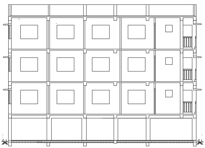
Now, its time for Dimension.
- Select the Layer pdf_text for the various dimension.
- Type 'D' or Dimension Style
- Select the size of the arrow as 250 and text height as 300.
RESULT: -