Creating a Layout, Section and Elevation with dimensions using AutoCad
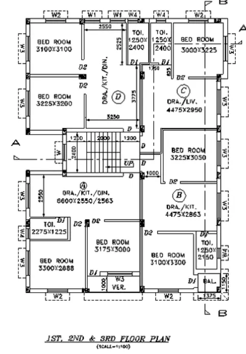
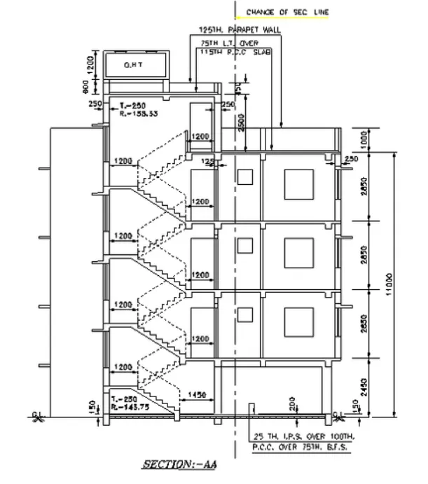
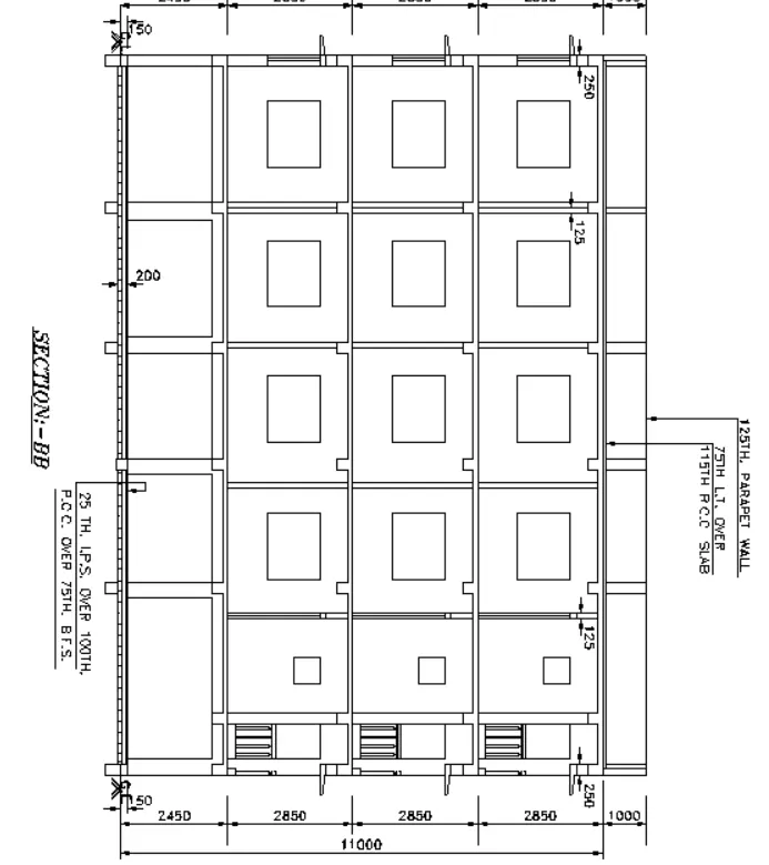
1) Create the Plan and Sections as shown in the Figures. Use proper dimension techniques and dimension styles to document the project. Assume the sizes of the doors and windows as per construction standards. Refer to sections for stair details if required.
introduction: AutoCAD consists of a number of drawing and modification tools. Among the modification toolss are
chamfer,fillet,offset,object snap, rotate,copy.move,mirror,trim,entend and join Chamfer: A chamfer is an angled line that meets the endpoints of two straight 2D objects its a sloped transition between two surfaces or adjacent faces on a 3D solid. We type CHA for this tool in command bar
drafting a following tools by using following commands like, by using object snap elliptical command, by using arcs commands construction lines and ray tools, divide and measure tool, and by Using modity commands like mirror, trim, entand explode, lenghten, align, break and join command, and manage layers in autoCAD 2019
Fillet: The fillet command is used to create rounded edges between the adjacent lines and faces in 2D and 3D. It is also used to connect two tangent arcs in 2D.Type F
Offest: Creates concentric circles, parallel lines,
and parallel curves.Type O in the command bar
Object Snap: Object snaps provide a way to specify precise locations on objects whenever we are prompted for a point within a command.Type OS in the command bar
Rotate: Rotates objects around a base point. Wcan rotate selected objects around a base point to an absolute angle. We type RO and rotate the object accordingly
Copy: Copies objects a specified distance in a specified
direction.We can enter C in the command line
Move: Moves objects a specified distance in a
specified direction.Type M in the command bar
Mirror: Creates a mirrored copy of selected objects. Wcan create objects that represent half of a drawing, select them, and mirror them across a specified line to create the other half. Type MI in the command bar
Trim: Trims objects to meet the edges of other objects.
Type TR in the command bar.
Extent: Extends objects to meet the edges of other objects.It extend objects, first select the boundaries. Then press Enter and select the objects that you want to extend. To use all objects as boundaries, press Enter at the first Select Objects prompt
Join: Joins the endpoints of linear and curved objects to create a single object, it combines a series of finite linear and open curved objects
Join: Joins the endpoints of linear and curved objects to create a single object, it combines a series of finite linear and open curved objects at their common endpoints to create a single 20 or 3D object. The type of object that results depends on the types of objects selected, the type of object selected first, and whether the objects are coplanar
INITIALLY:
Start by typing ONEW in the command box
• Advanced Setup > Set the Units, Angle, Angle measure, Angle direction and area.
After settings provide the lower limit and upper limit.
Now we can start the sketching.
Commands used:
1. XL-V OR XL-H.
2. Offset.
3. Fillet.
4. Extend
5. Trim.
Aim:
To Create the Plan and Sections as shown in the Figures. Use proper dimension techniques and dimension styles to document the project using AutoCAD.
Procedure:
Step 1:
In the command prompt type units > mm.
• In the command prompt type limmax > 100,100 • In the command prompt type limits > 0,0
• In the command prompt type zoom > a
Step 2:
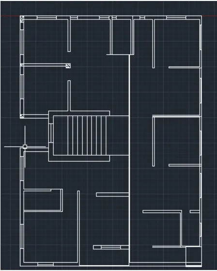
• In the command prompt type XL to draft the infinite line ⚫ In the command prompt type offset to offset it to the
disired distance
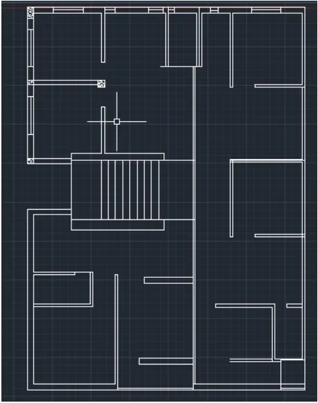
With the command lines, offset and trim windows are drawn
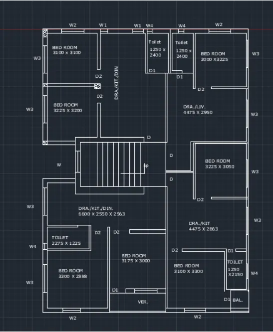
In the ribbon tab > annotate > mtext (to text the annotations)
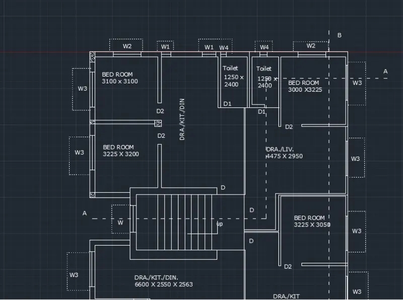
In the command prompt type LN (linetype) to get dotted lines
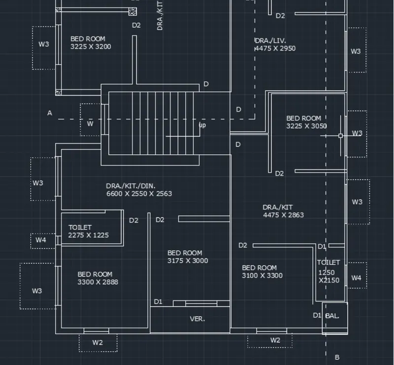
In the ribbon bar › dimensions > to give the dimensi
to the plan
• In the ribbon bar > hatch > sand
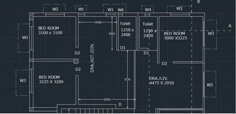
Final Result:
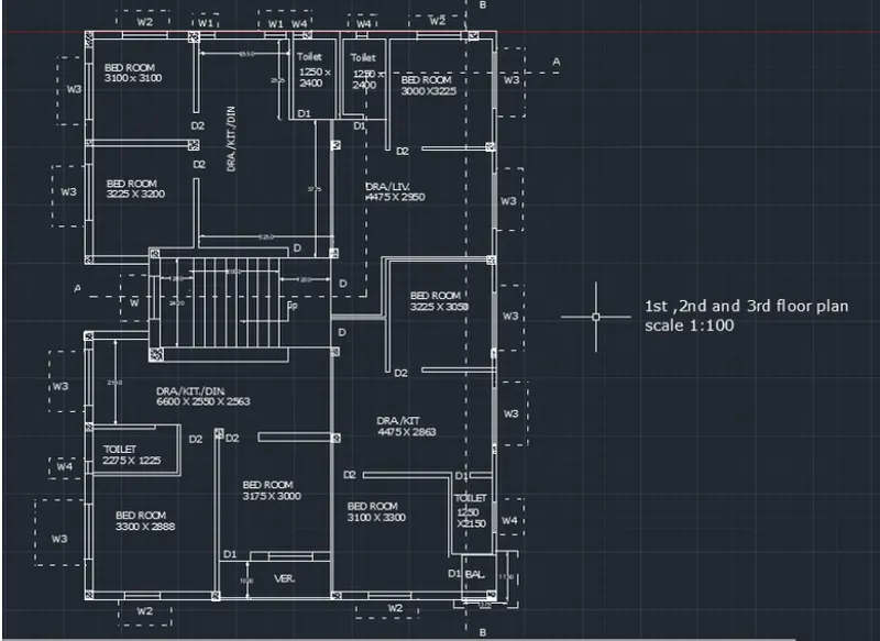
1) b. Create the Plan and Sections as shown in the Figures. Use proper dimension techniques and dimension styles to document the project. Assume the sizes of the doors and windows as per construction standards. Refer to sections for stair details if required.
AIM:
To create section A-A of the previous plan
Procedure:
• In the command prompt type rec to draft the rectangle
of dimensions 2745 x 1200
• In the commnd prompt type offset and offset it to the
required distance
In the command prompt type to draft the required
lines
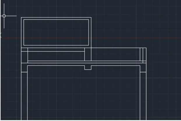
In the command prompt type LT( to get the dotted lines
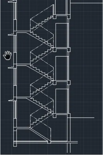
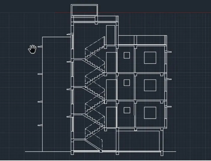
In the ribbon tab> annotate > to text the plan
• In the ribbon tab > Dimensions > to give the dimensions
to the plan
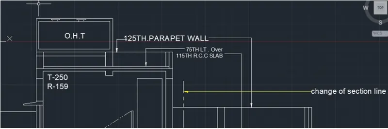
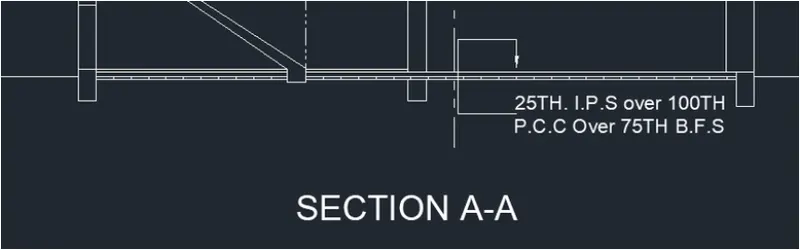
• In the command prompt type leader to type the given
text and dimensions
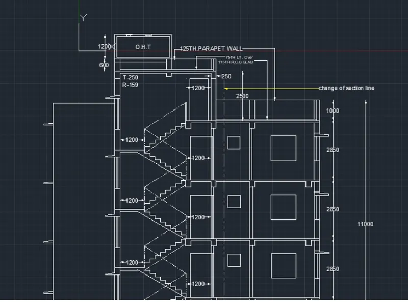
final result:
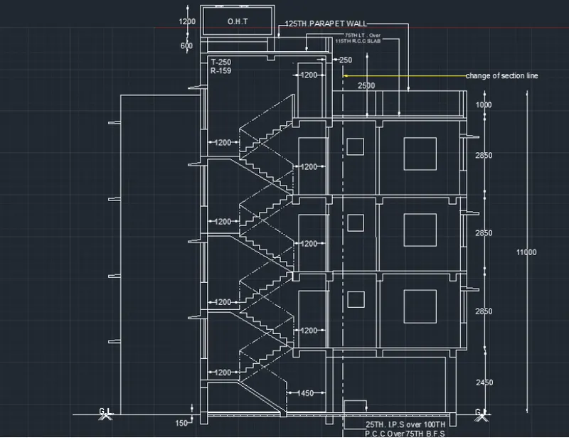
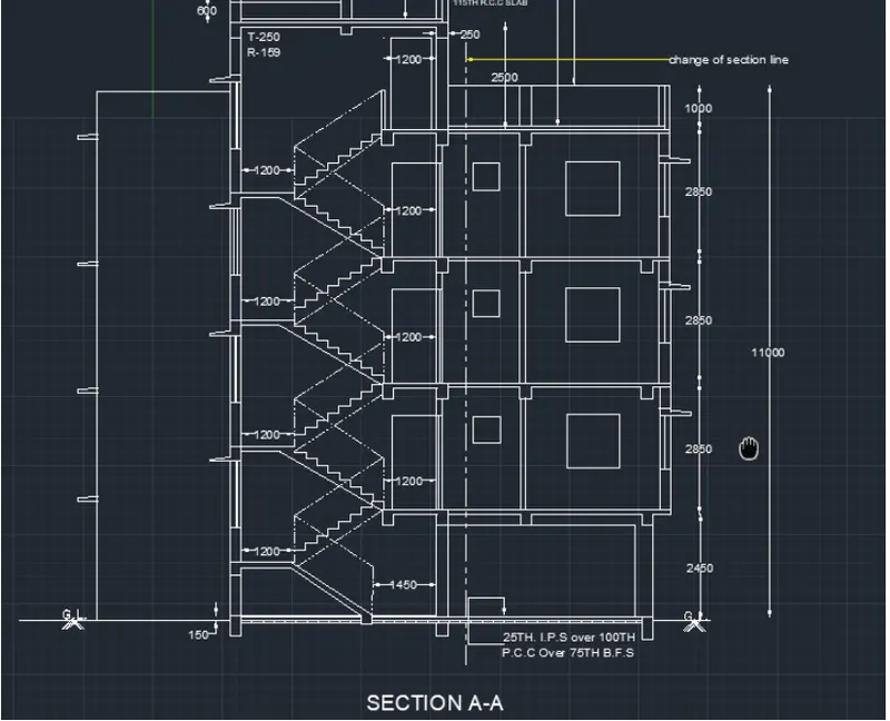
1)c. Create the Plan and Sections as shown in the Figures. Use proper dimension techniques and dimension styles to document the project. Assume the sizes of the doors and windows as per construction standards. Refer to sections for stair details if required.
AIM:
To create section B-b of the previous plan
PROCEDURE:
• In the command prompt type XL to draw the infinite lines
• In the command prompt type offset to offset the infinite lines for the desired distance
• In the command prompt type rec to draw the
rectangles
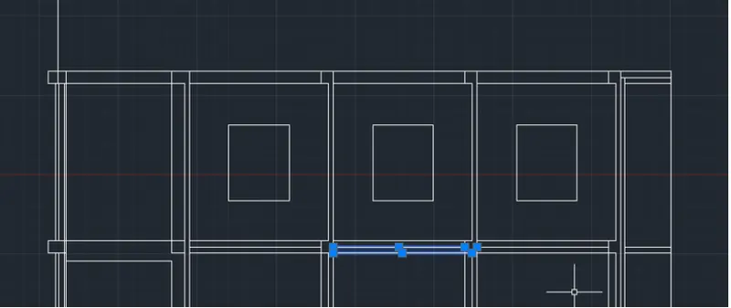
In the command prompt type line to draft the desired
lines
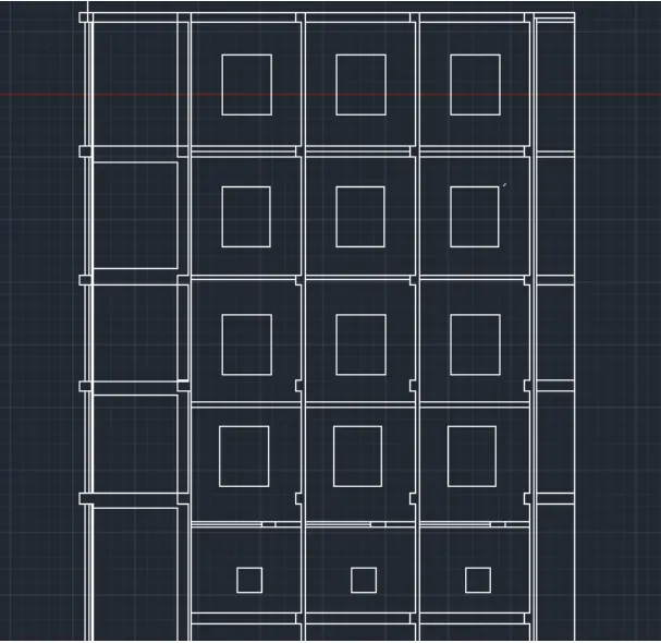
In the command prompt type dimensions to give the
dimensions • In the command prompt type leader to give the
annotations for the plan
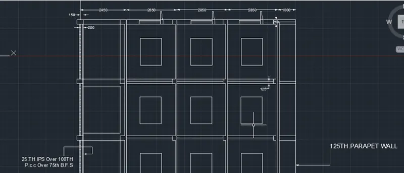
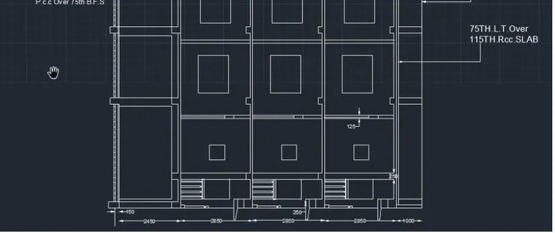
final result:
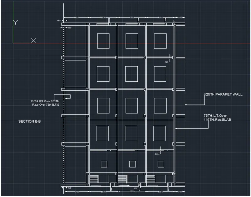
Conclusion:
ALL RESULT OF EACH DRAWING HAS BEEN ATTACHED WHICH WAS TAKEN FROM AUTOCAD