Creating a Layout, Section and Elevation with dimensions using AutoCad
Aim:
To create the floor plan and sections given in the picture and use proper dimension techniques and dimension styles to document the project.
Procedure:
- Open the new drawing in Autocad and set metric and limits as 0,0 and 100000,10000.
- Then set the units as desimal and precision as 0.
- Now start creating the plan with construction line horizontal and vertical.
- Then offset both the lines at a distance of 230mm and using fillet, trim command trim the unwanted lines.
- Offset the vertical line at 3300mm then offset at 100mm and then 3175mm and 100mm and 3100mm and 100 and then 1250mm and then finally 230mm.
- Now using the offset command offset the 2nd bed room outer wall at 1000mm and then 230mm.
- Offset the 1st bed room outer wall line at 2888mm and 100mm and then 1225mm and finally 100mm. Then lower part of the plan consisting of 3 bed rooms are created.
- Then offset the toilet wall line at 2550mm and second bed room line at 2563mm. Then offset the lines at 230mm.
- Offset the stair wall at 2400mm then 230mm and outside wall at 2000mm and 100mm.
- Now create the stairs line of thread 250mm and the landing of both sides as 1200mm.
- Then offset the 3rd bed room wall line at 2863mm and 100mm and then 3050mm and 100mm.
- Now offset the right side outer wall line at 3225mm and 100mm. Then using the fillet and trim command remove the unwanted lines. The center bed room is created.
- offset the bed room wall line at 2950mm and 100mm and then 3225mm and 230mm.
- Then offset the right side wall line at 195mm and 230mm. Now trim the line used to offset.
- Then offset the line at 3000mm and 150mm and then 1250mm and 100mm and then 1250mm and 100mm and then 2550mm and 100mm and then 3100mm and 230mm. Remove the unwanted lines using trim and fillet command.
- Now offset the top right side wall line at 3100mm and 100mm and then 3200mm. Top side bed rooms, dining, toilets are created.
- Then create the doors and windos at required places to the following sizes,
D1=762mm W1=1000mm W4=725mm
D2=915mm W2=1200mm
D =1150mm W3=1400mm
- Create the sunshade lines at the place of windows.
- Then place the columns of size 230*300mm at the required places in the plan.
- Use dimension line to create dimension lines at all the sides and set the dimension styles as text style-arial and over all scale 50.
- Using text styles, create a text style as arial and height of text is 200. Create a text at the required places.
- The floor plan is created.
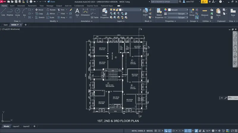
- Now to create the section A-A.
- Create the construction lines at the columns that visible in the section of the plan.
- Then create the horizontal construction line in the lower part form the plan.
- Offset the line at 50mm this is the ground level and again offset it at 75mm and at 175mm and 120mm. The 120mm is the finished floor level of ground floor.
- Offset the floor level line at a distance of 2450mm, this is the first floor level.
- Then offset the line bleow at 115mm the ground floor slab is created.
- Then offset the right side column line at 1450mm and create the steps riser as 143.75mm and thread as 250mm. Dog legged staircase is created.
- Using the trim and fillet command remove the unwanted lines. Ground floor is created.
- Offset the ground floor slab at 2850mm, this is the second floor level.
- Then offset the slab line below at 115mm and offset the right side column at 1200mm and create the steps, riser as 158.33mm and thread as 250mm. Create a dog legged stair case.
- Then create construction line of windows and door from the plan, create the windows in the first floor.
- Copy the first floor and place it over and over to create two more floors.
- Then offset the terrace floor slab line at 2500mm and then 450mm to create the head room.
- Then above the head room cerate a over head tank of height 1200mm.
- Then using dimensions create a dimensions at the palces to know the measurements.
- Using multi leader to create a leader with text in needed place.
- The section A-A form the plan is created and the over all height of the building is 12000mm.
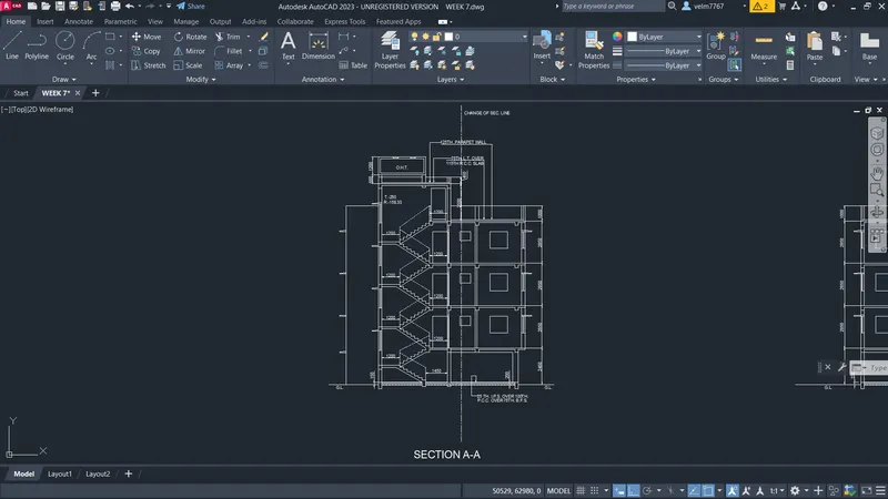
- Create the secion B-B form the floor plan.
- Now create a construction lines from the floor plan where the section is made.
- Then create the horzontal construction line.
- Offset the line at 50mm this is the ground level and again offset it at 75mm and at 175mm and 120mm. The 120mm is the finished floor level of ground floor.
- Offset the floor level line at a distance of 2450mm, this is the first floor level.
- Then offset the line bleow at 115mm the ground floor slab is created.
- Then create a beams at the colums and the beam line projecting from the plan.
- Then offset the ground floor slab line at a distance of 2850mm, this is the second floor level.
- Create a beams at the colums and the beam line projecting from the plan.
- Now project the construction lines from the plan where the windows are placed.
- Then create the windows and sunshades.
- Create a hand rails at the balcony side.
- Then copy the first floor and place over it to make two more floors.
- Then offset the third floor slab line at a distance of 1000mm and create the lines of columns projecting.
- Using trim commnd to remove the unwanted lines.
- Then using dimensions create a dimensions at the palces to know the measurements.
- Using multi leader to create a leader with text in needed place.
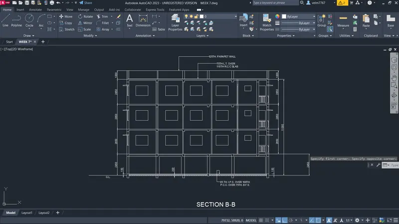
- The section B-B form the plan is created and the over all height of the building is 12000mm.
Result:
The floor plan and sections are created as shown in the pictures. The proper dimension techniques and dimension styles are used to document the project.
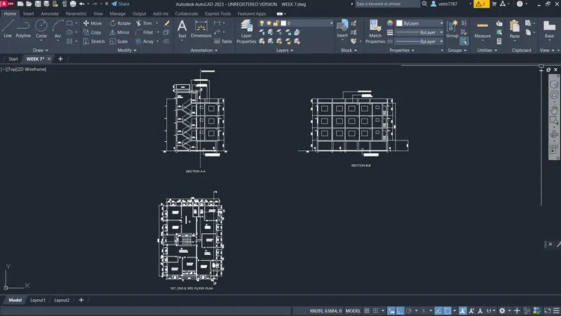
Note: The drawing attachment is given for the reson of dimensions are not clearly visible in the picture.