Creating a Layout, Section and Elevation with dimensions using AutoCad
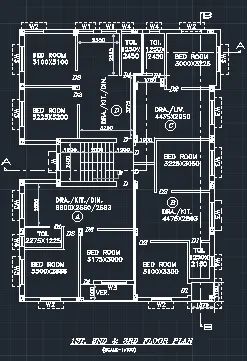
AIM: To create Plan and Sections given in the figure in AutoCad using various drafting tools and using proper dimension techniques as per the given drawing showing the doors and windows of proper sizes as per construction standards.
PROCEDURE: The procedure of drafting the Plan and Sections is given below along with the step wise sceenshots of the drawings.
- Set up the drawing for Metric units
- Set up the limits of drawing according to the available drawing sizes.
- Set up the Zoom extents.
- Set up the dimensions to Decimal units.
- Import the given PDF drawings to Autocad for reference as shown in below screenshot.
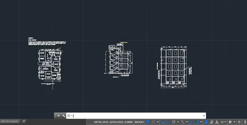
- Scale up the imported drawing as per the drawing scale as shown in the screenshot below.
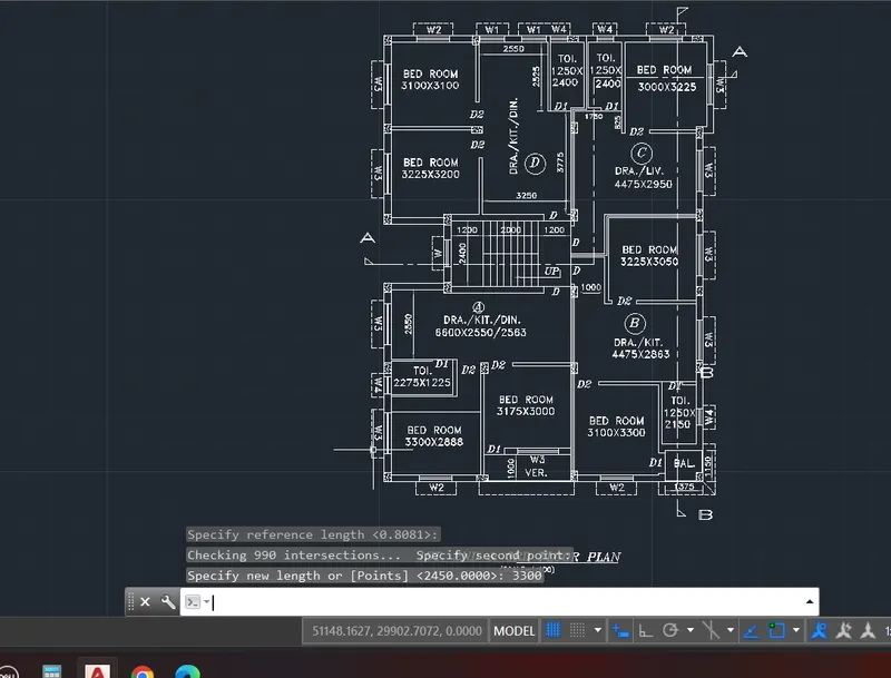
DRAWING PLAN PROCEDURE
- Start the drawing by using line command, copy command and draw the inner lines of the rooms.
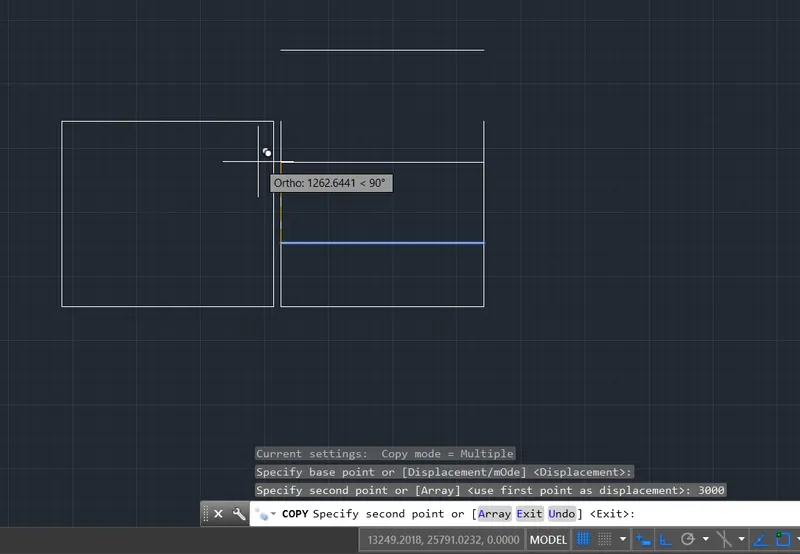
- Copy the lines and shift new line to form the wall thickness.
- Fillet the corners of rooms using Fillet command.
- Trim the unwanted lines using Trim command.
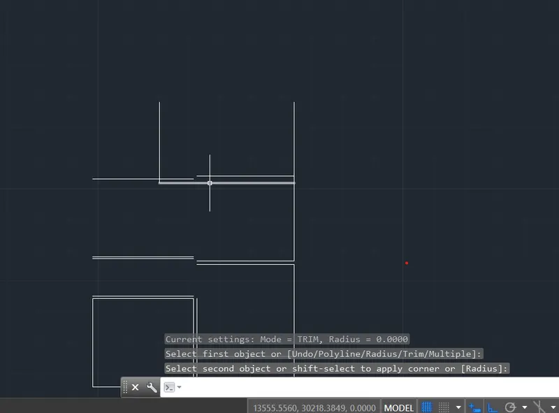
- Extend the lines to meet the required lines as per drawing using Extend command
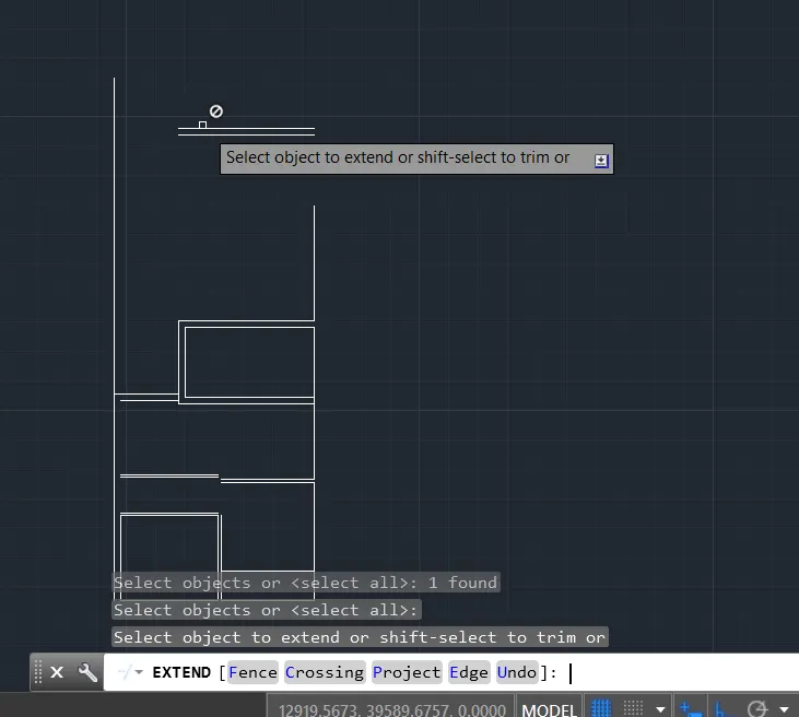
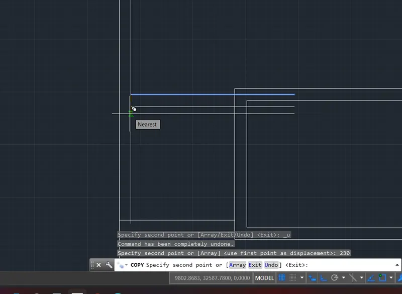
- Using copy command copy the lines and shift as per the room dimensions and thickness of walls.
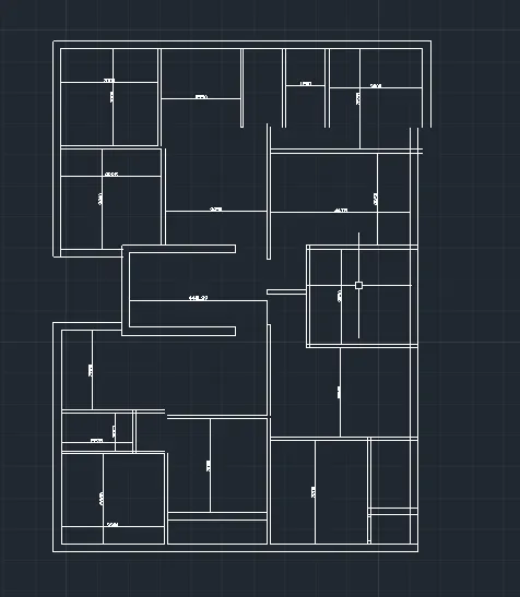
- All the rooms of the plan are drafted.
- Check the dimensions of the rooms to match the given drawing
- Draw the columns of given sizes using Rectangle command.
- Copy the columns and change the orientation of the column
- These column rectangles will be used for inserting in the drawing as per the column positions in given drawing.
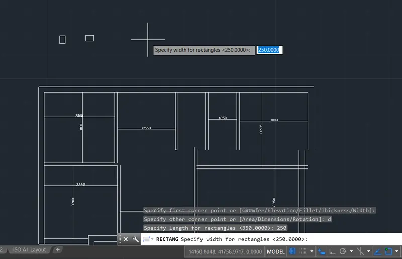
- Draw the columns of all the required sizes.
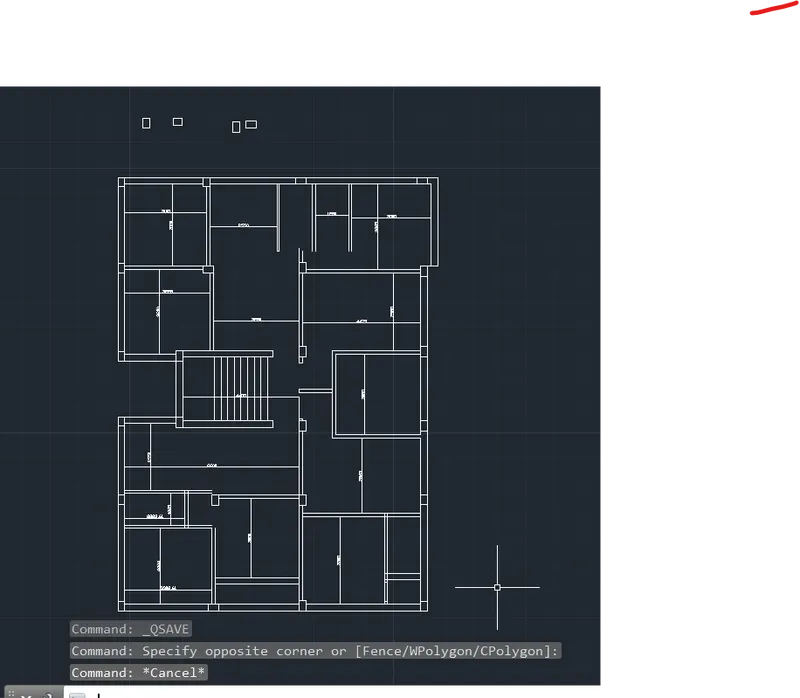
- Draw the typical window drawings along with the sunshade and use the line types according to given drawing
- Using MText write down the window tag.
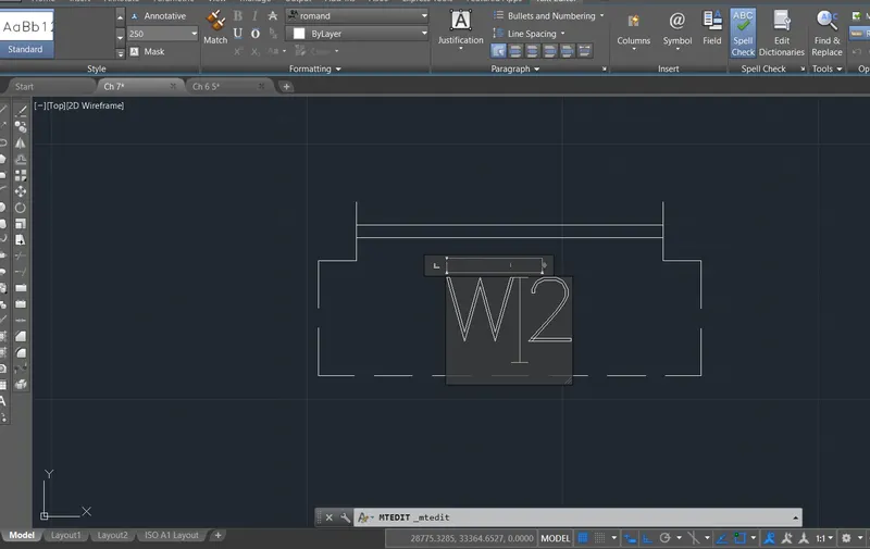
- Draft the windows of all the given sizes and tags for ready use in the drawing.
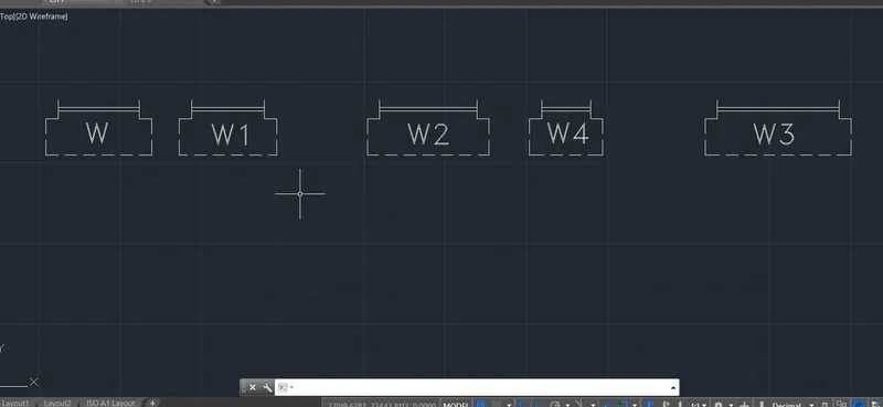
- Copy and pasted the windows in the plan as per the given positions and required orientations by rotating the window drawings.

- Using the MText and modifying the style and font to match the given drawing the Room names are provided along with dimensions.
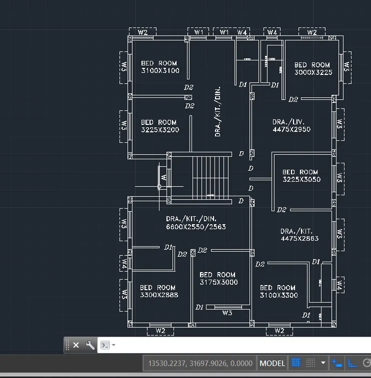
- Show the section lines AA &BB by changing the line type to centre line.
- The fonts of the AA & BB are also provide as per given drawing.
- Thus the PLAN drawing is completed which will be used for drawing the sections as per the section lines.
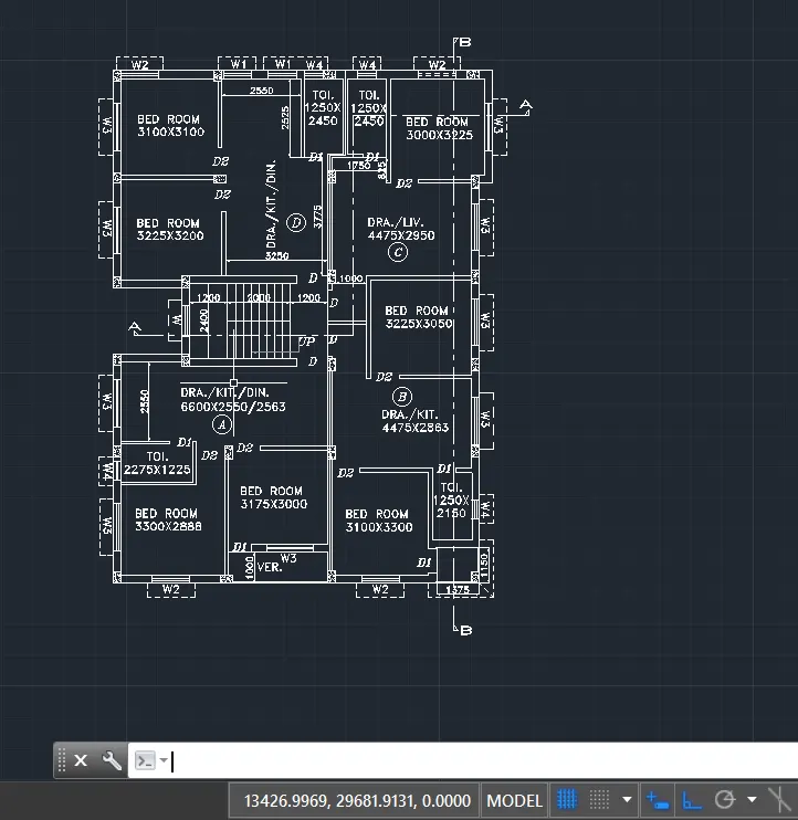
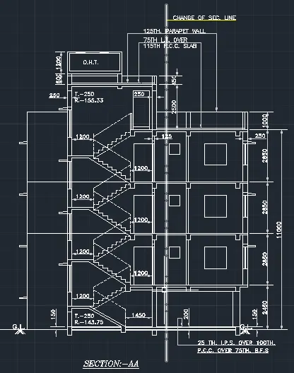
SECTION AA DRAWING PROCEDURE:
- Draw the rays from the plan corners, columns, windows as a reference for drafting the Section drawing
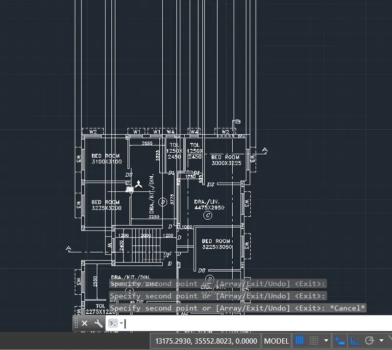
- Provide the ground line and the various slab levels by copying and shifting as per the given floor to floor dimensions.
- Draw the steps for first flight as per the given tread and riser dimensions
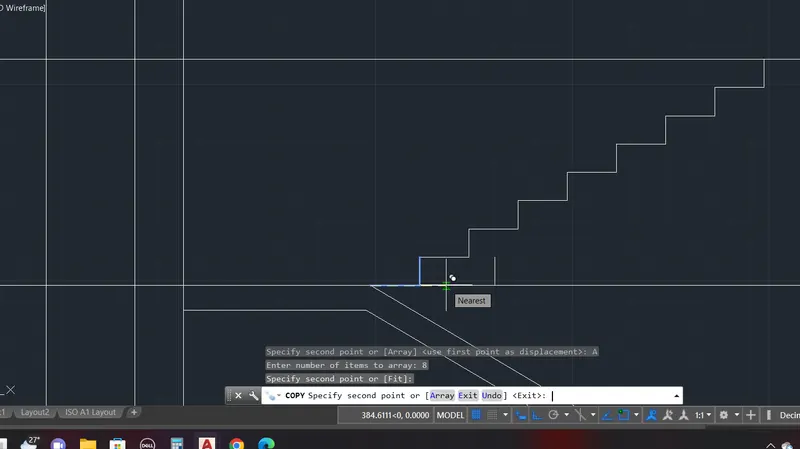
- Complete the staircase tread and riser section
- Provide the windows at one floor as per the given dimensions and reference positions
- Draw the below ground beams as shown in the figure
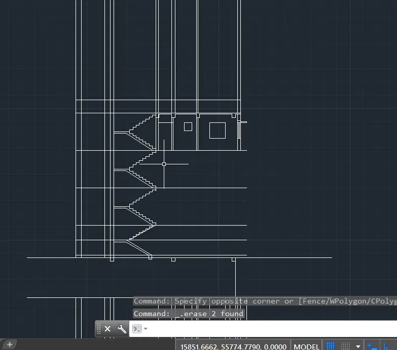
- Copy and shift the windows to other 2 floor.
- Draw the water tank as per given dimensions\
- Provide the Leader and the text using MLS command for modifying the multi leader style.
- Provide the dimenstions using Dimlinear and DimContinue commands as required
- Draw the window sections along with the sunshade sections.
- Show railing for staircase and change the line type to hidden.
- Thus the SECTION AA drawing is completed as shown below.
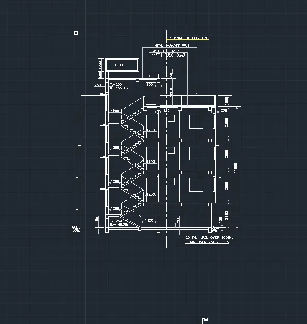
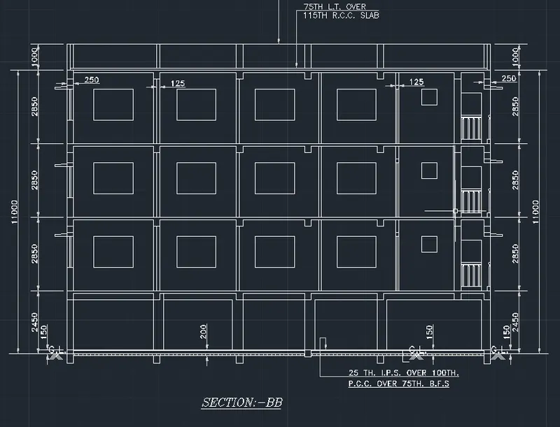
SECTION BB DRAWING PROCEDURE:
- Rotate the plan by 90degrees so as to easily draft the Section BB as shown in below screenshot.
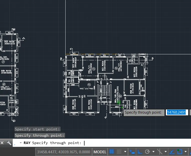
- Draw the Rays from the column, window, wall positions for the reference to draw Section
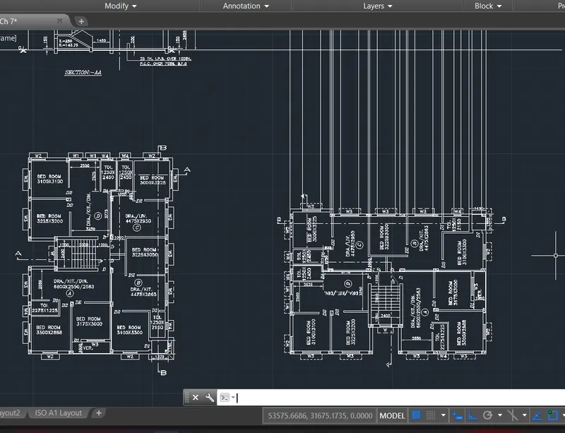
- Draw horizontal lines and copy and shift as per the floor to floor heights
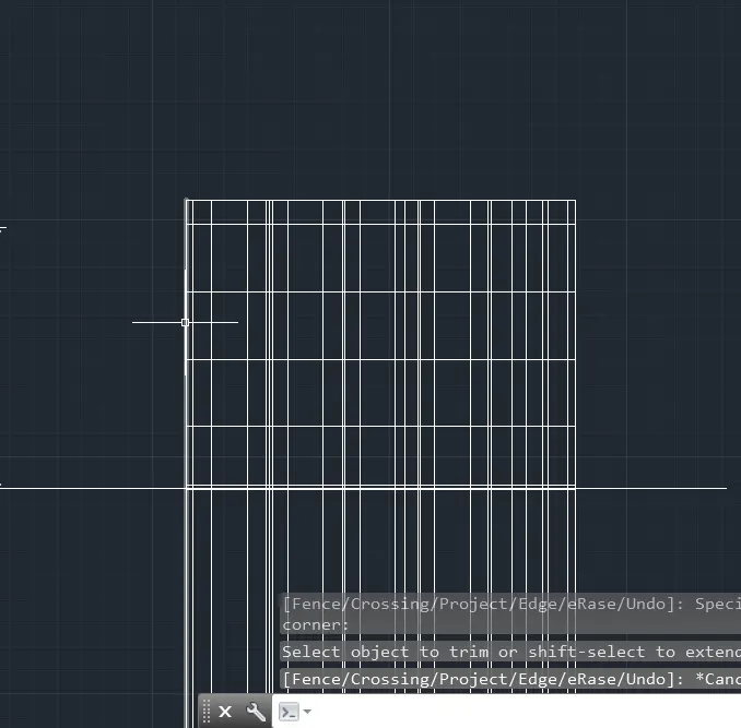
- Trim the unwanted Rays
- Draw the Windows for one floor as per the given drawing and using the Ray reference lines.
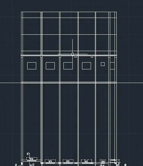 \
\
- Draw the beams for one floor as show in the drawing.
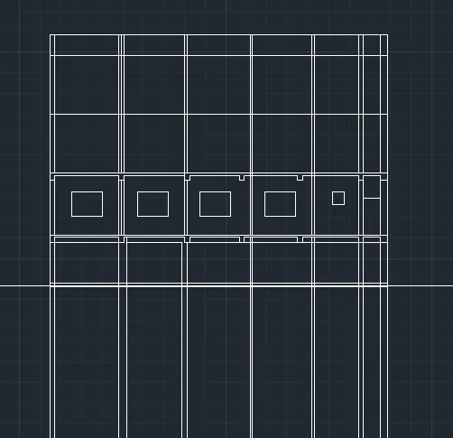
- Copy and shift the windows, beams, window section, sunshade and balcony railing details to other floors as shown in the below screenshot
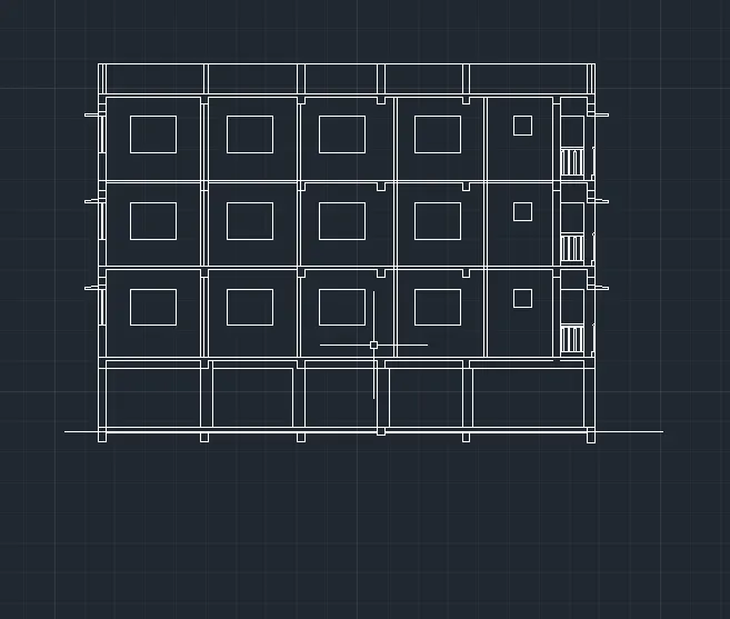
- Provide the dimensions and the text details as shown in the drawing
- Thus the final SECTION BB drawing is completed as shown in below screen shot
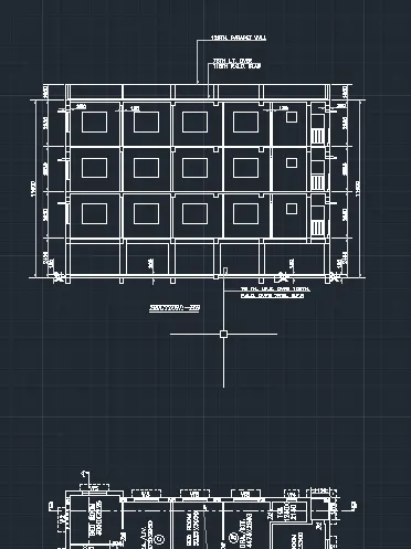
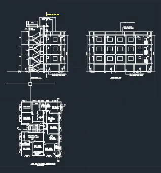
- Final Plan, Section AA and Section BB drawings are shown below in screen shot.
- FINAL PLAN DRAWING
- FINAL SECTION AA DRAWING
- FINAL SECTION BB DRAWING
CONCLUSION: Thus using various drawing tools in autocad the given Plan and Sections are drafted.Various commands including the Leader, dimensions style, etc were used for drafting the drawing and the step wise screenshots of procedure are attached for reference along with the final completed drawings.