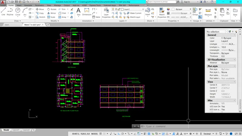
Creating a Layout, Section and Elevation with dimensions using AutoCad
Aim :- To draw the Plan, Elevation and Section of the building by using AutoCAD Software
Introduction :-
The general commands used for drawing the building is as follows :
- Line
- Polygon
- Rectangle
- Circle
- Erase
- Copy
- Trim
- Mirror
- Offset
- Extend
- Move
The dimensions:
- For external wall – 250mm
- For internal wall – 125mm
- For Staircase : - Treads : 250mm, Rise : 150mm
The assumed dimensions :
For Windows:
- W – 1000 X 1500
- W1 – 900 X 1200
- W2 – 1200 X 1200
- W3 – 1500 X 1200
- W4 – 700 X 500
For Doors:
- D – 1000 X 2000
- D1 – 750 X 2000
- D2 – 900 X 2000
Procedure :-
- Click on AutoCAD application and open this application
- Type QNEW in command bar and enter
- Select default setting as Metric
- In default setting click on use a wizard and in that advance setting and set unit as decimal and precision as 0 and press Next
- Set Angle as Decimal Degree and precision as 0 and click next
- Set Angle Measure as EAST and press NEXT
- Set Angle Direction as Counter-Clockwise and press NEXT
- Set Area by providing Length as 50 and Width as 50
- Press finish
- Keep ortho, Object snap >ON
- Keep Snap and Grid > Off
- Un+enter
- Type > Decimal, Precision > 0
- Units to scale inserted content > milimeter
- Enter
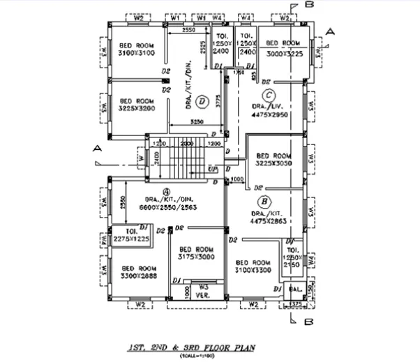
Plan
- Take xline command
- Put xline horizontal and xline vertical
- Trim the negative coordinates
- Give the offset of 250mm to show the external wall thickness
- Offset the horizontal line at a distances of 1150, 3138, 3550, 4488, 7413, 9463, 9713, 12788, 12913, 16388
- Give offset to each above horizontal lines as per their wall thickness
- For internal wall give offset of 125mm and for external wall give offset of 250mm
- Offset the vertical line at a distances of 3475, 3675, 5975, 6850, 7350, 8725, 10325. 11700
- Give offset to each above vertical lines as per their wall thickness
- For internal wall give offset of 125mm and for external wall give offset of 250mm
- Give the another required offsets by using offset command
- Leave the spaces for doors as per its dimension
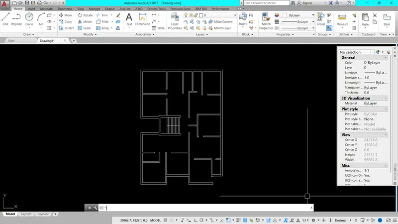
- Take trim and erase command to remove the unwanted data as shown below
- Click on layer properties
- Click on new layer
- Give the layer name > Wall
- Turn the layer ON
- Set Unlock
- Slect layer colour > Red
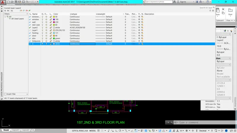
- Similarly, use this above process to provides the layer
- The layers which are assigned are shown in below fig
- By using Line command
- Provide the windows and doors as per their respective dimension
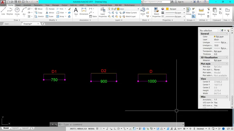
For Doors:
- D – 1000
- D1 – 750
- D2 – 900
- Take the rectangle command to show the column
- Specify its first corner anywhere out of drawing
- Select dimension
- Take length as 250 and Width as 400
- Take hatch command
- Click on dropdown
- Select hatch style as AR CONCR
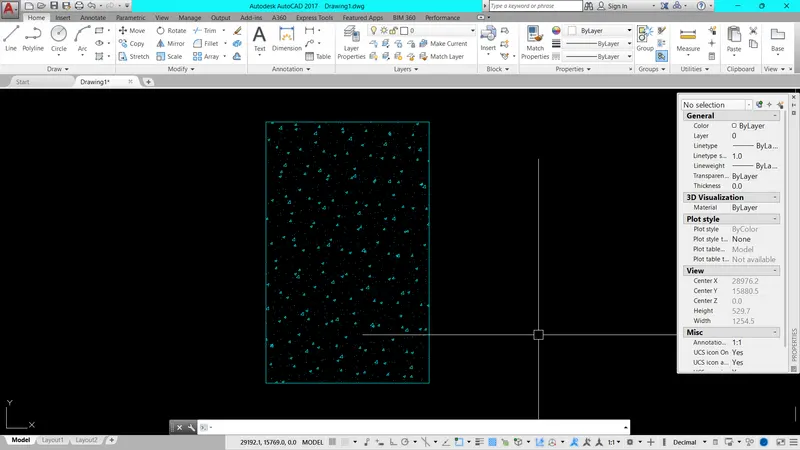
- Click inside the rectangle
- It will show you following results
- Take the copy command
- Select the object > by clicking this above columns
- Paste this columns wherever it is required
- Select this column
- Take rotation command
- Select base point as centre of column
- At specify rotation angle as 90
- Take the copy command
- Select the object > by clicking rotated column
- Paste this columns wherever it is required as shown below
- For window shade
- Slect the dash line layer
- Click on line type > Other
- Load > Select ACAD_ISO03W100
- Global scale factor > 8
- Enter
- Use line command to show the window shade as shown below
- Similarly use this above procedure to provide the window shade for other windows
- To create the text
- Click on Annotation tab >multi line
- Manage textile > New
- Style name as > Challenge 7 Plan> OK
- Font Name > Arial
- Height > 200
- And press set current
- Use multiline text
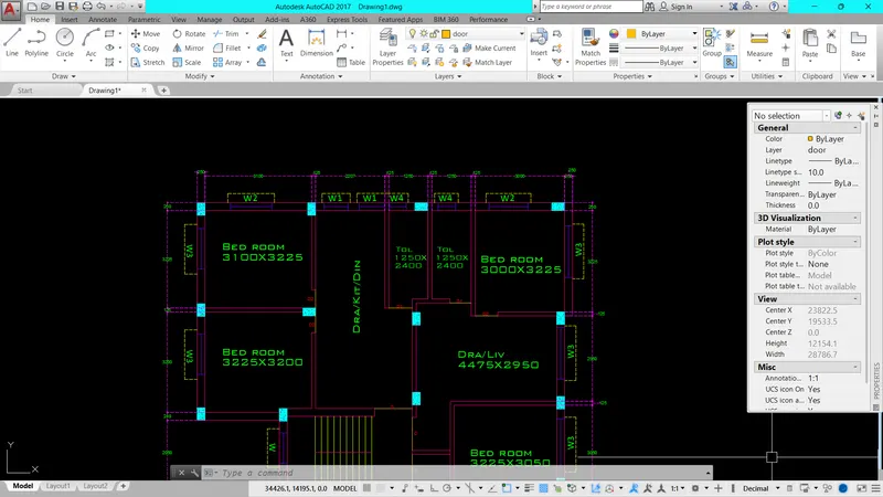
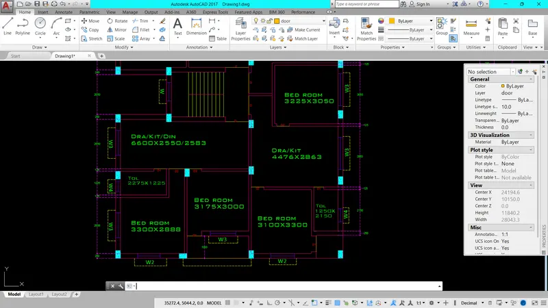
- And fill the required text in drawing as shown below
- Click on ANNOTATION tab
- Click on Dimension
- Click > Manage dimension style
- Style name > Challenge 7 Plan
- Set the characteristics of dimensions as
- Select the yellow colour for the dimension style and extension line
- Select arrowhead size as 100
- Select the text as Cyan colour
- Select Text Style > Challenge 7 Plan
- Text Height > 200
- Then select linear dimensions
- Provide the linear dimension having height 250mm
- Then take continuous dimension command
- And provide continuous dimension
- Provide at the required place just like shown below
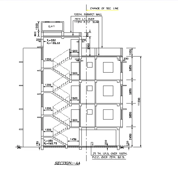
Section AA
- Take the xline command
- Select > Vertical
- Specify the points required to take projection for section AA
- Take the perpendicular line as shown below
- Offset the horizontal line at 150 and 125 at top
- Offset the horizontal line at 50 at bottom
- Offset the top offset line at distance of 125mm at bottom
- Change the current layer to slab layer
- Offset the top offset at a distance of 2450 keeping curser upward
- From the last offset take the offset of 2850
- From the last offset take the offset of 2850
- From the last offset take the offset of 2850
- From the last offset take the offset of 1000
- Trim the unwanted lines as shown below
- Give the slab thickness of 125 by using offset command as shown below
- Change the current layer to Doors and Windows layer
- Offset the top line of first floor
- At distance of 800 to show the window seal level
- Offset the last offset at 1200 to show the window height
- Trim the unwanted lines
- Similarly show the W2 = 1200 X 1200 windows at other floors
- Similarly show the W4 = 700 X 500 windows at other floors as shown below
- Offset the wall near stairs at a distance of 1450
- Keep Object snap on
- For Ground Floor
- For first flight
- Take line command
- Select the starting point of the stairs
- Specift length as 143.75 by keeping curser towars the northe
- Specift length as 250 by keeping curser towars the West
- Specift length as 143.75 by keeping curser towars the northe
- Specift length as 250 by keeping curser towars the West
- Continue this process till reach to the landing
- For next flight also, do same procedure as mentioned above
- The flight which are hidden, select that flight
- Properties > Select line type as > ACAD_ISO03W100
- Set global scale as 5
- For Remaining all floors
- Take line command
- Select the starting point of the stairs
- Specift length as 158.33 by keeping curser towars the northe
- Specift length as 250 by keeping curser towars the West
- Specift length as 158.33 by keeping curser towars the northe
- Specift length as 250 by keeping curser towars the West
- Continue this process till reach to the landing
- For next flight also, do same procedure as mentioned above
- The flight which are hidden, select that flight
- Properties > Select line type as > ACAD_ISO03W100
- Set global scale as 5
- Use the line command to show the hand rails as shown below
- Take the rectangle command
- Specify first corner point anywhere out of drawing
- Specify dimension as
- Length- 1000 ,Width – 2000
- Copy that rectangle
- Paste that rectangle wherever it is necessary as shown below
- Use the line command and offset command
- Provide the window in the section wall
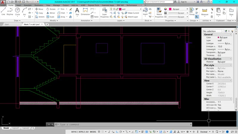
- i.e W3 = 1500 X 1200 as shown below
- Use the line command and offset command
- Provide the window in the staircase wall
- i.e W = 1000 X 1500 as shown below
- Take the rectangle command
- Specify corner anywhere out of drawing
- Select dimension
- 250 X 250
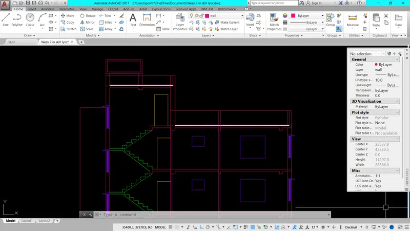
- Copy that rectangle to the positions where beams are provided as shown below
- Trim the side of rectangle as per requirement as shown below
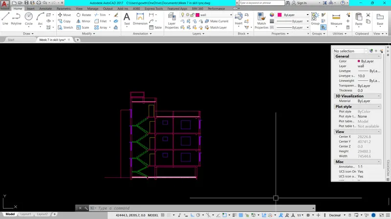
- Click on ANNOTATION tab
- Click on Dimension
- Click > Manage dimension style
- Style name > Section AA
- Set the characteristics of dimensions as
- Select the yellow colour for the dimension style and extension line
- Select arrowhead size as 100
- Select the text as Cyan colour
- Select Text Style > Section AA
- Text Height > 200
- Then select linear dimensions
- Provide the linear dimension having height 2450mm
- Then take continuous dimension command
- And provide continuous dimension
- Provide the dimension at the required places just like shown below
- And the section AA is ready
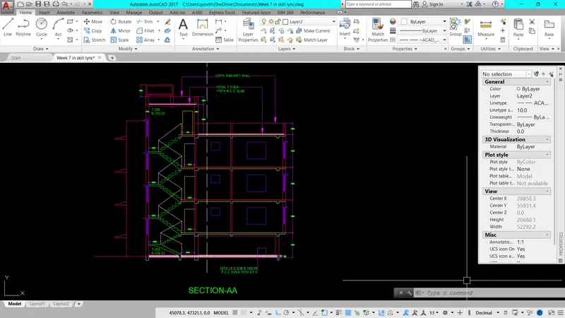
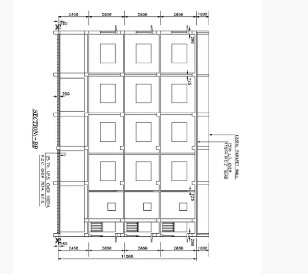
Section BB
- Take the xline command
- Select > Horizontal
- Specify the points required to take projection for section AA
- Take the perpendicular line as shown below
- Offset the horizontal line at 150 and 125 at Right side
- Offset the horizontal line at 50 at Left
- Offset the top offset line at distance of 125mm at Left
- Change the current layer to slab layer
- Offset the right offset at a distance of 2450 keeping curser rightside
- From the last offset take the offset of 2850
- From the last offset take the offset of 2850
- From the last offset take the offset of 2850
- From the last offset take the offset of 1000
- Trim the unwanted lines as shown below
- Give the slab thickness of 125 by using offset command as shown below
- Change the current layer to Doors and Windows layer
- Offset the top line of first floor
- At distance of 800 to show the window seal level
- Offset the last offset at 1200 to show the window height
- Trim the unwanted lines
- Similarly show the W3 = 1500 X 1200 windows at other floors
- Similarly show the W4 = 700 X 500 windows at other floors as shown below
- Specify corner anywhere out of drawing
- Select dimension
- 250 X 250
- Copy that rectangle to the positions where beams are provided as shown below
- Use line command to show the chajja
- Trim the side of rectangle as per requirement as shown below
- Use the line command to show the handrail
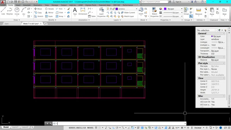
- Click on ANNOTATION tab
- Click on Dimension
- Click > Manage dimension style
- Style name > Section BB
- Set the characteristics of dimensions as
- Select the yellow colour for the dimension style and extension line
- Select arrowhead size as 100
- Select the text as Cyan colour
- Select Text Style > Section BB
- Text Height > 200
- Then select linear dimensions
- Provide the linear dimension having height 150mm
- Then take continuous dimension command
- And provide continuous dimension
- Provide the dimension at the required places just like shown below
- And the section BB is ready
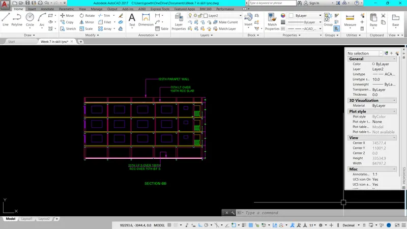
Result:
- Plan
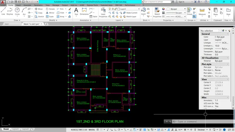
- Section-AA
- Section-BB
- Total