Creating a Layout, Section and Elevation with dimensions using AutoCad
1. Aim: To design the plan and section as in the given attachment.
Introduction: To design the plan and section by using proper dimension techniques and dimension styles to document the project.
Procedure:
- First before drawing we need to set the units as per the drawing requirement.
- Then also we need to set limits by entering limmax by giving X and Y direction points.
- After entering first we need to draw the plan and then plan to section.
- Before starting the plan we need to understand the plan and we have to assume some dimensions.
- In the plan they have given only room dimensions so we need to draw the plan with room dimensions only.
- Then as per the construction standards we need to assume inner and outer wall dimension, door dimensions and window dimensions.
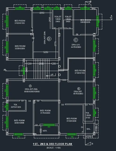
- By taking the room dimensions for the plan first part to be drawn as per the below attachement.
-
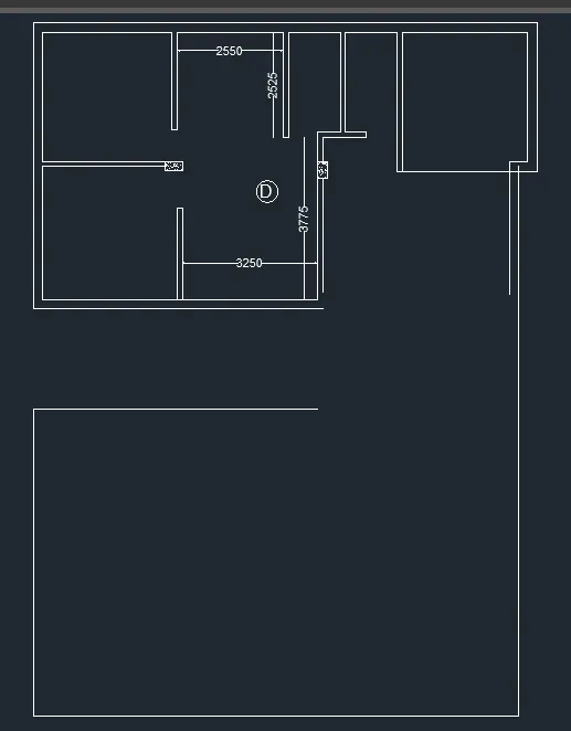
- After taking the first part room dimensions, there is a staircase given at the centre portion.
- We need to draw the staircase with the given dimensions and by assuming tread height in the staircase.
- Then with the first part we haave to draw the beside part by taking inner room dimensions and wall thickness.
- Then after drawing the room dimensions we need to mention the room names with dimensions as shown in the drawing.
-
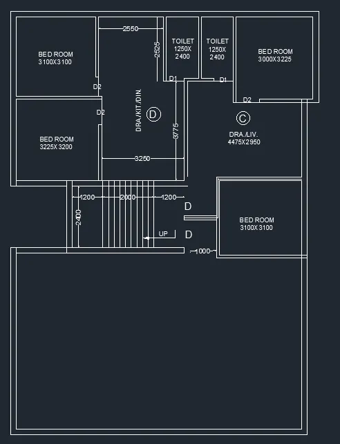
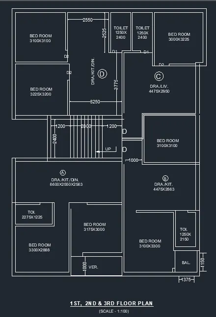
- Then by using the same procedure we have to draw all the room with the given dimensions.
- Then as per the dimensions we have to mention the room and door portions wherever required.
- In this we have to assume the door dimensions as per the construction standards.
- In this plan. there are 4 different types of doors and we have to take 4 different door dimensions.
- Also the door portion has to be trimmed whereever required as shwon in the below drawing.
-
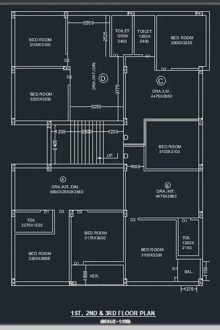
- Then after placing the rooms, doors and windows then we have to show the column portions.
- But there is no column sizes given in the plan attachment.
- Column portiions is already given in the attachment with hatching portion also.
- So we have to assume column sizes and we have to place them as shown in the below attachement.
-
- And now after placing the column portions we have to show windows.
- There is no sizes for window given in the plan and there are 4 different types of windows in the plan.
- So as per the cconstruction standards we have to assume the window sizes also.
- After assuming, place the window portions wherever required given in the plan.
- Then finally there is a section line cutting in the plan and we have to show that as in the given attachment.
- Also the final drawing is ready and is attached in the result.
-
- After completing the plan, then we need to draw the section also.
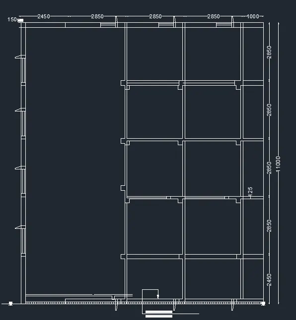
- For this section, by usnig Xl line we have to draw the lines for walls and column portions.
- Then from that we have to take walls and column portions wherever shown in the plan.
- Then at the starting level there is plinth level shown in the section.
- And the height of the floor is to be mentioned in the section drawing as the height is already given in the attachment.
- So as the height and distances are given in the section, by using reference lines in the plan we need to draw the outer prtion of the section.
-
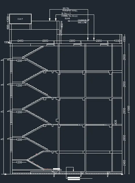
- In the same way, there is a stair case shown in the section as in th plan.
- So for this we have to first design separately the staircase and have to place that in the section.
- In this staircase we need to show the tread and risers in the staircase with the proper height as given in the plan.
- Also there is a landing with the distance shown in the drawing.
- And there is a Over head water tank shown in the terrace area with the distances shown in the below drawing.
-
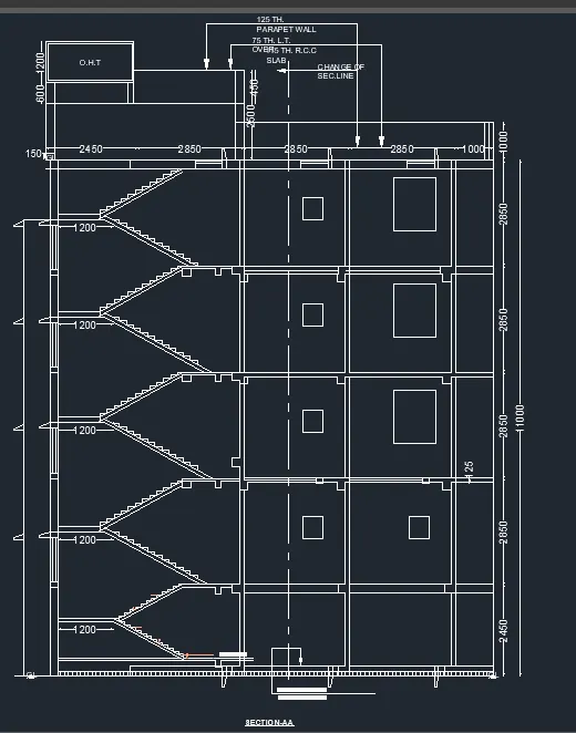
- Finally as in the given plan there is a cutting portion shown in the plan.
- With this cutting portion, we need to mention the doors and window portions cuting section in the drawing.
- Then there is a window portion shown in the outer wall portion inside the wall.
- Also there is a lintel for the window shown in the outer window portion of the wall.
- Then by showing all the cutting portion final section is ready as attached in the below.
-
- After completing the section AA, then we need to draw the section-BB also.
- For this section, by usnig Xl line we have to draw the lines for walls and column portions.
- Then from that we have to take walls and column portions wherever shown in the plan.
- Then at the starting level there is plinth level shown in the section.
- And the height of the floor is to be mentioned in the section drawing as the height is already given in the attachment.
- So as the height and distances are given in the section, by using reference lines in the plan we need to draw the outer prtion of the section.
-
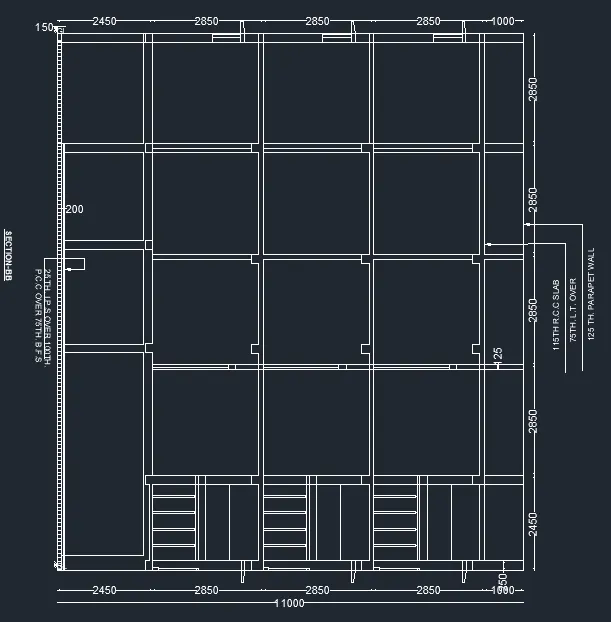
- In this sectional drawing, the view of section is changed.
- As the sectional view is changed from that direction only we need to draw the section.
- As in the section cutting portion, there is a cutting portion in the doors and windows.
- We have to show them in the floor area where the window or door is placed as shown in the below drawing.
-
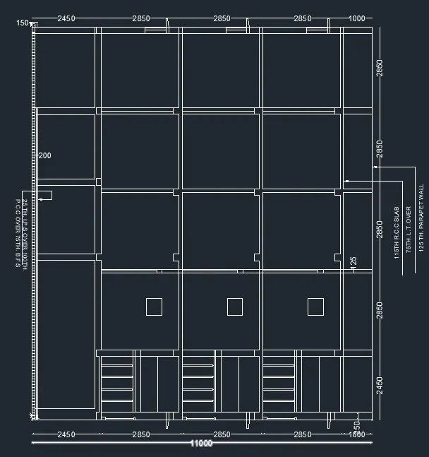
- Finally as in the given plan there is a cutting portion shown in the plan.
- With this cutting portion, we need to mention the doors and window portions cuting section in the drawing.
- Then there is a window portion shown in the outer wall portion inside the wall.
- Also there is a lintel for the window shown in the outer window portion of the wall.
- Then by showing all the cutting portion final section is ready as attached in the below.
-
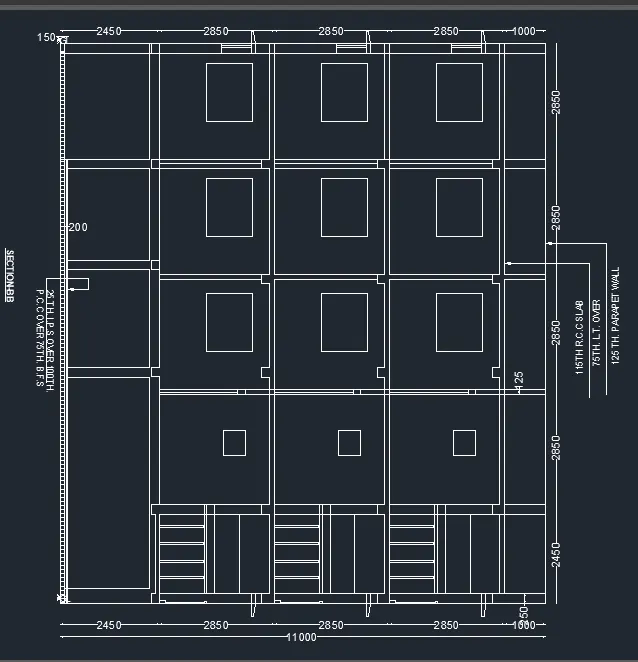
Result for Plan:-
Result for Section AA:-
Result for Section BB:-
Note: There are 3 attachments attached for the Plan, Section-AA, Section-BB for the clear view of Text and dimensions.