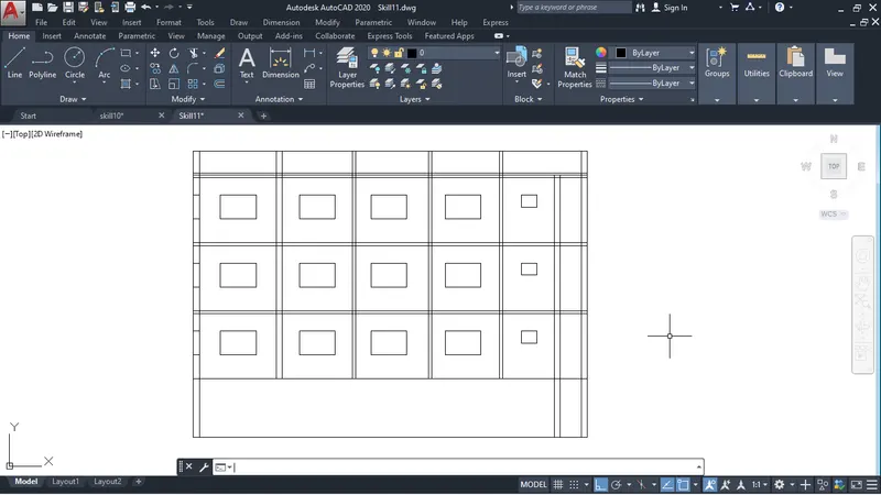
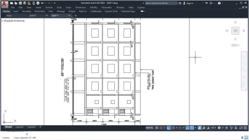
Creating a Layout, Section and Elevation with dimensions using AutoCad
Aim: Create the plan and section using proper dimension techniques and dimension styles
I am using template imperial
Set the unit in mm by command- UN
and set the dimension style by command-D
and creat the floor plan
Assume the door and window size
D1=650x2024
D2=875x2024
D=1000x2024
W1=900x900
W2=1200x1000
W3=1500x1200
W4=650x500
W=1000x1200
All dim. in mm
lets draw
I use the line tool to draw a line
first I draw line vertical then horizontal
then i take offset of 250mm to create outer wall
I created a left and top of the outer wall
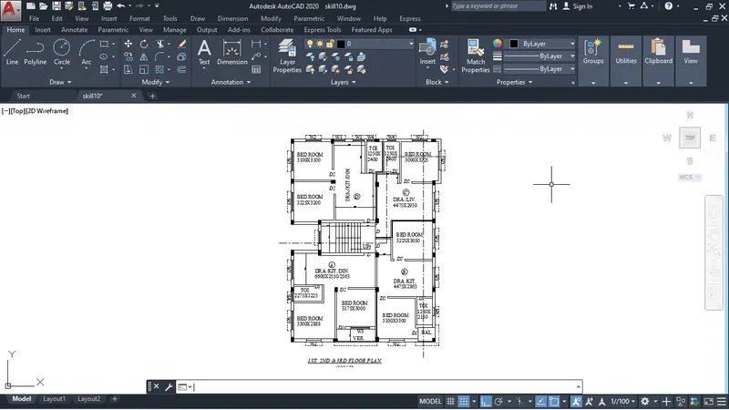
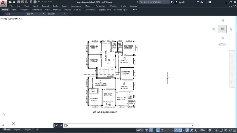
after we create first room 3100mmx3100mm it is left in corner as you can in below fig.
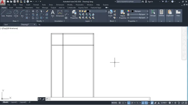
Similarly with help of offset we can draw inner wall (125mm), toilet and other room in right corner
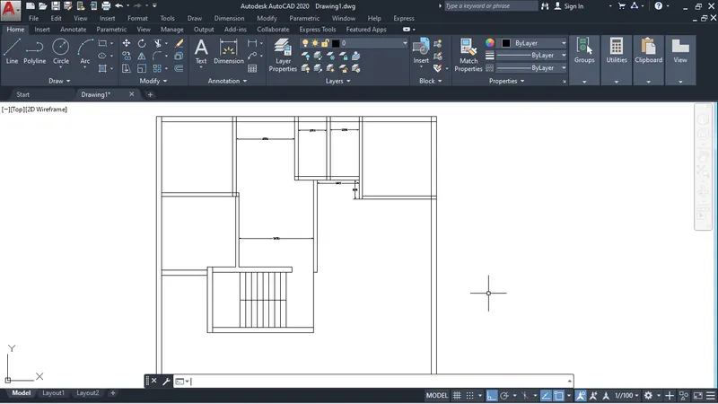
we take offset step by step according to sizes and we can draw all rooms, toilet , stairs.
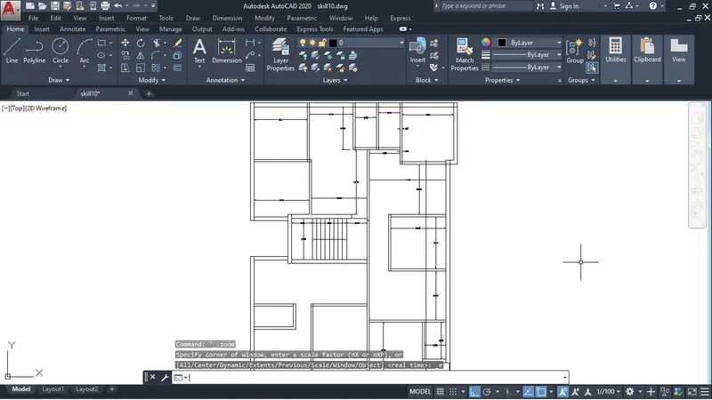
After making all rooms , toilets, stairs we draw the windows and doors as above sizes are mension for windows and doors
After draw the column (250mmx350mm)
and give the position of column
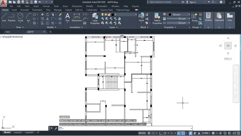
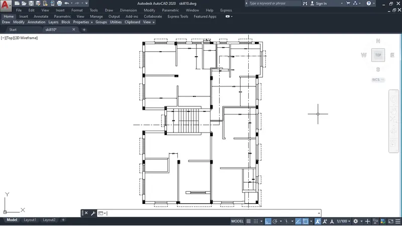
after making windows we give the chajja for every windows
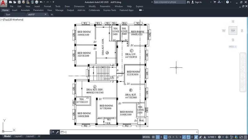
After chajja i use text command-Mtext (we can use any single line text or multiline text)
I have given the hight 200 and used verdna font
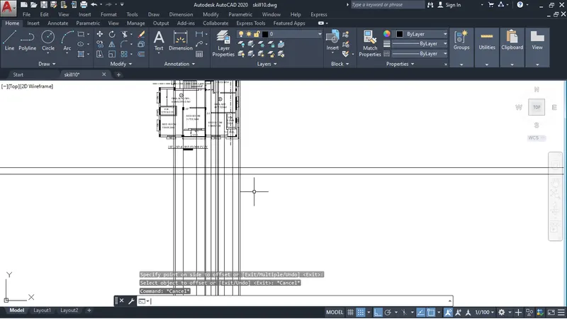
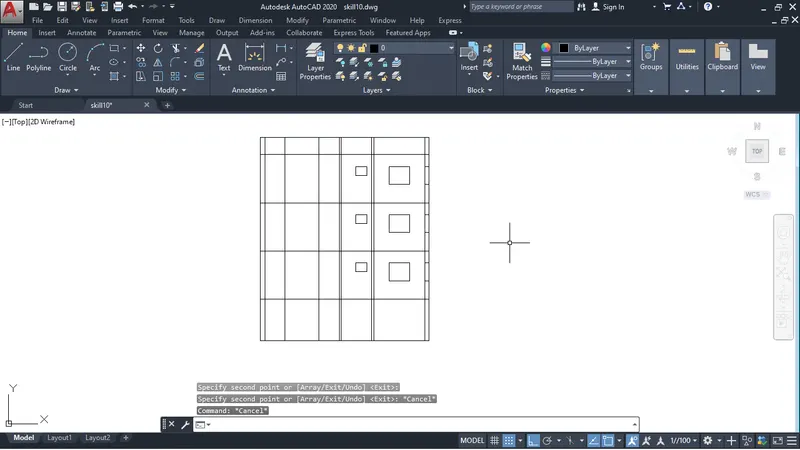
For SECTION-AA I construction line
Command for construction line- XL enter
after entering we can use vertical (V-enter) and horzontal (H-enter) line
I use line tool to draw stairs
I have given the Riser-143.75 and Tread-250 this for ground floor to first floor
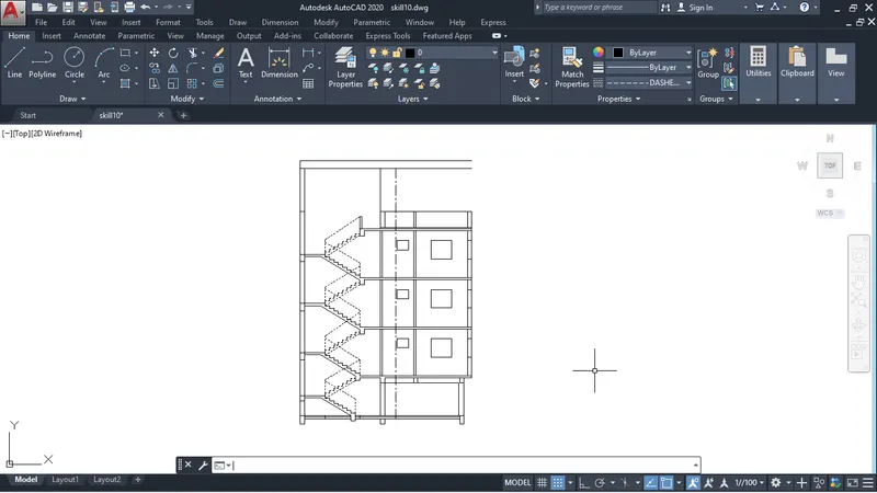
After that first floo to scond floor and for other floor Riser-158.33 and Tread-250mm
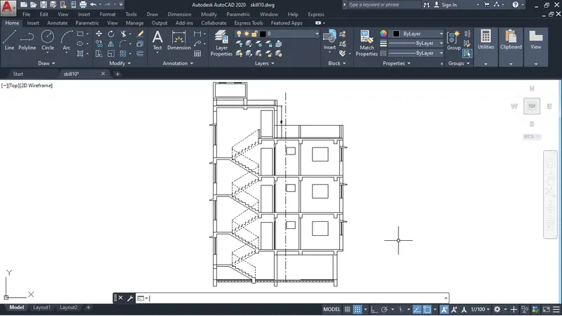
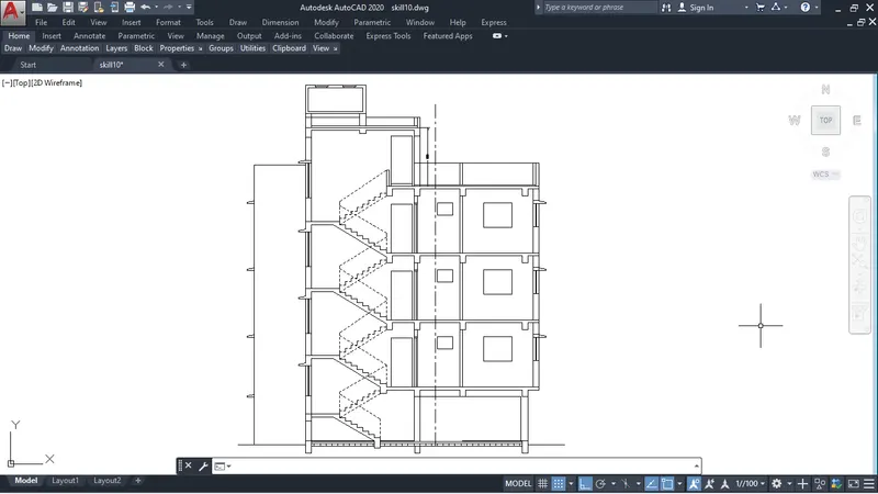
also used multileader for details of slab thickness
Multileader command- MLD
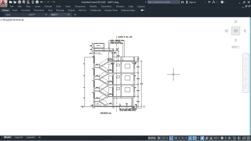
For SECTION-BB also use construction line by command-XL enter for horizontal H-enter for vertical V-enter
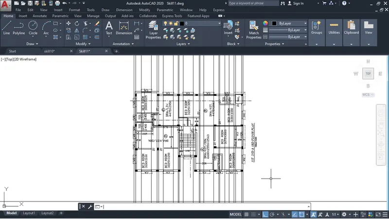
I rotated the floor plan to draw side elevation of drawing.
To rotate command-RO