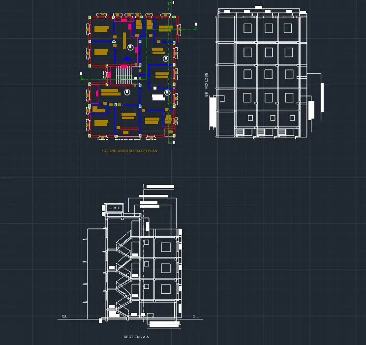
Creating a Layout, Section and Elevation with dimensions using AutoCad
AIM
To Create the Plan and Sections as shown in the Figures.
INTRODUCTION
- A plan drawing is a drawing on a horizontal plane showing a view from above
- An elevation drawing is drawn on a vertical plane showing a vertical depiction
- A section drawing is also a vertical depiction , but one that cuts through space to show what lies within
COMMANDS USED
- Unit command
- Limit command
- Line command
- Offset command
- Trim command
- scale command
- Rectangle command
- Dimlinear command
- Mtext command
- Dtext command
- Dimstyle command
- Move command
- Copy command
- Divide command
- Object snap command
PROCEDURE
STEP 1
- Open a new file
- In the command line type units , select the units and also set the precision
- In the command line type 'LIMITS' and specify the limits at lower left corner and upper right corner as
- Then zoom all
STEP 2
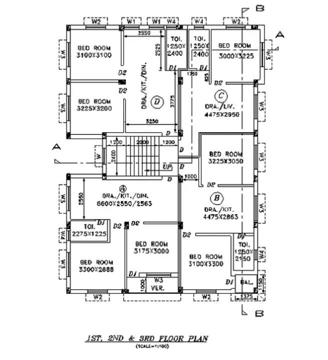
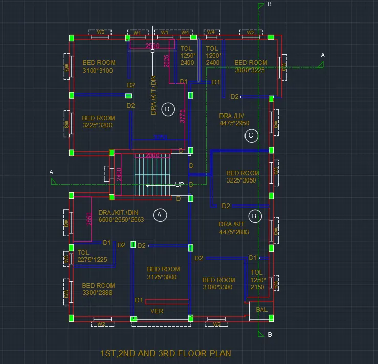
floor plan of 1st,2nd and 3rd floor
- By using line , construction line, offset and trim command ,with the given dimension
- First drawing bedroom of size 3100*3100
- Next we draw another bedroom of size 3225*3200
- Next we draw the drawing/kit/din room with the size of 2550*3775*3250
- Next we draw two toilets of size 1250*2400
- Next we draw bedroom of size 3000*3225 in the part c
- Next we draw the drawing/liv room with the size of 4475*2950
- Next we draw toilet of size 1250*2150
- Next we draw bedroom of size 3100*3300
- then we are leaving somespace for verandah and again drawing bedroom of size 3300*2888
- Next we draw toilet of size 2275*1225
- Next we draw the drawing/kit/din room with the size of6600* 2550*2563
- last we are drawing stair case of size 3200*2400 ,tread is 250mm and riser is 143.75
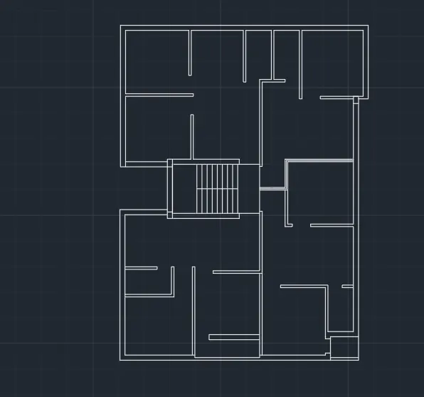
- next we have to trim the unwanted lines
- then place the column where ever required
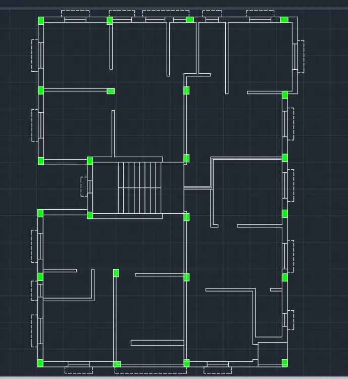
- Ater that we have to mark the window and door openings according to the standard
- here we taken as
- W1-900*1200
- W3-1200*1200
- W2-1000*1200
- W4-600*900
- W-600*1200
- DOORS
- D1-700*2100
- D2-900*2100
- D-1200*2100
- using multiline text texts are written
- using dimlinear command dimensions are provided
- load the dotted lines and make it as current and draw the section lines
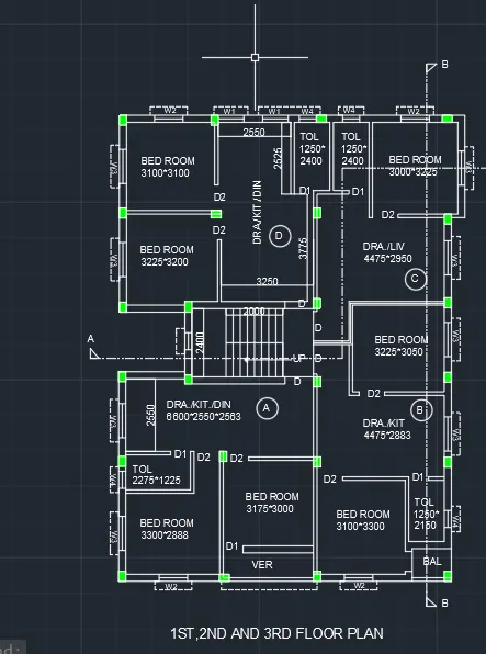
- Using the layer command layers are provided
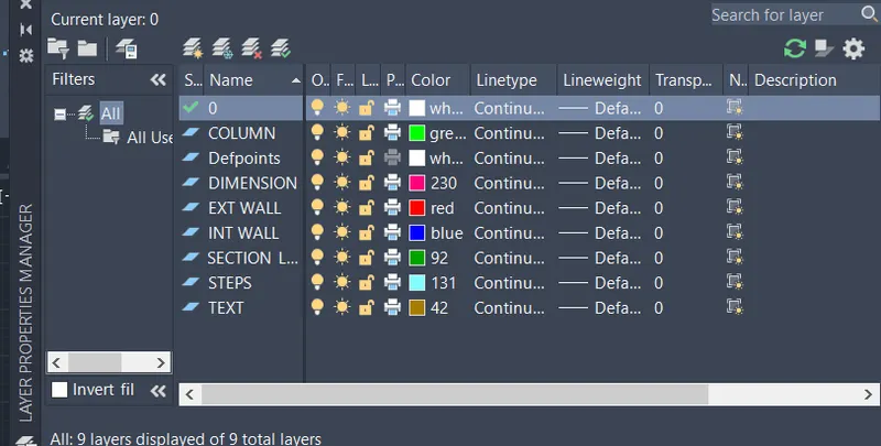
STEP 3
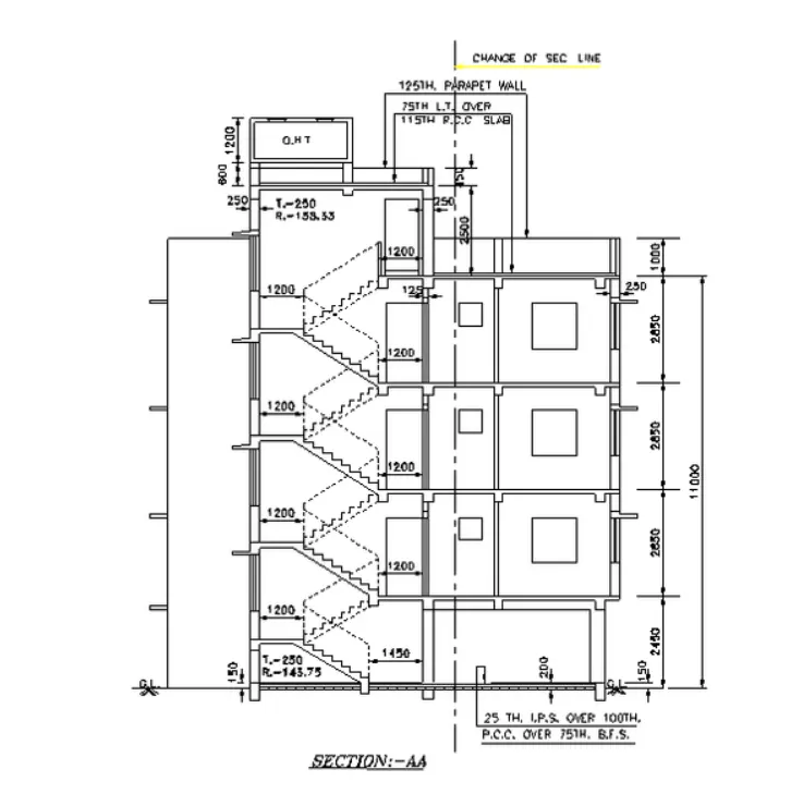
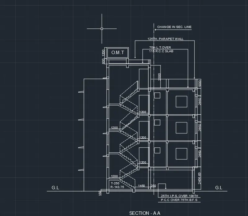
drawing section - AA
- using the construction line that is Xline command extend the line from the plan in downward direction inorder to create projections
- from ground level offset 150mm
- then offset 2450 for ground floor
- then offset 2850 for 2nd floor
- then offset 2850 for 3rd floor
- then offset 1000 for parapet wall
- offset 2500 from terrace level to mumty
- offset 600 and 1200 for O.T.H
- then we have to draw the staircase with 250 tread and 143.75 riser
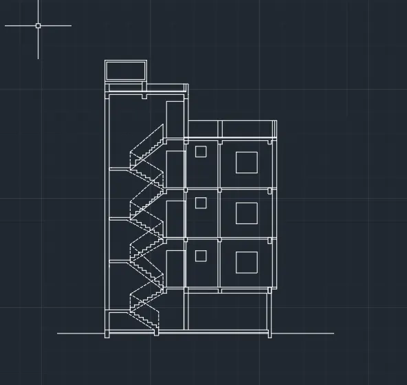
- according to the standard size draw the windows and chajjas
- dimensions are marked using dimlinear and dimcontinous
- text using multiline text
STEP 4
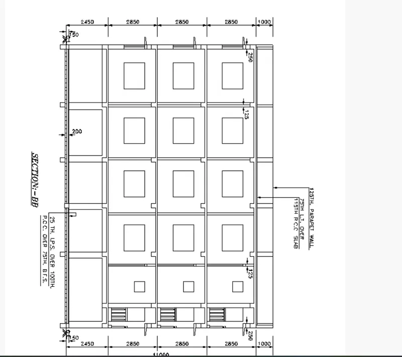
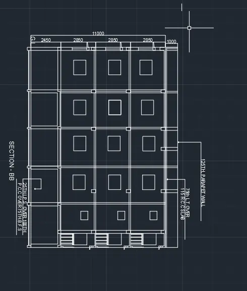
drawing section - BB
- using the construction line that is Xline command extend the line from the plan in inorder to create projections
- projection of all internal wall taken as 125mm and external wall as 250mm
- first of all draw a line vertically which is the baseline of the section
- then offset 150mm from base line
- then offset 2450 for ground floor
- then offset 2850 for 2nd floor
- then offset 2850 for 3rd floor
- then offset 1000 for parapet wall
- thickness of slab is assumed as 150mm
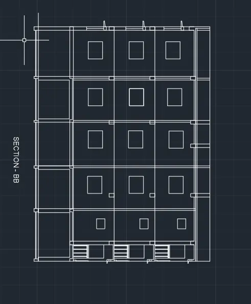
- according to the standard size draw the windows and chajjas
- dimensions are marked using dimlinear and dimcontinous
- text using multiline text
RESULT
using autocad plan and sections are drawn using proper dimension technique and dimension styles