Creating a Layout, Section and Elevation with dimensions using AutoCad
- AIM: To create plan, section , elevation as shown in figure by using proper dimension and technique and dimension style to document the project and also assuming the sizes of doors and windows as per
construction
- INTRODUCTION
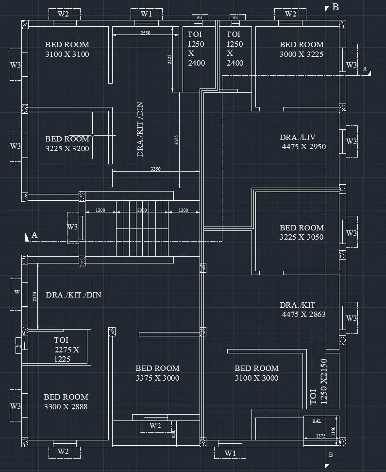
- The plan which was given in figure -1 was a floor plan of the building
- The given plan floor plan includes all 1st ,2nd ,3rd floors of the building
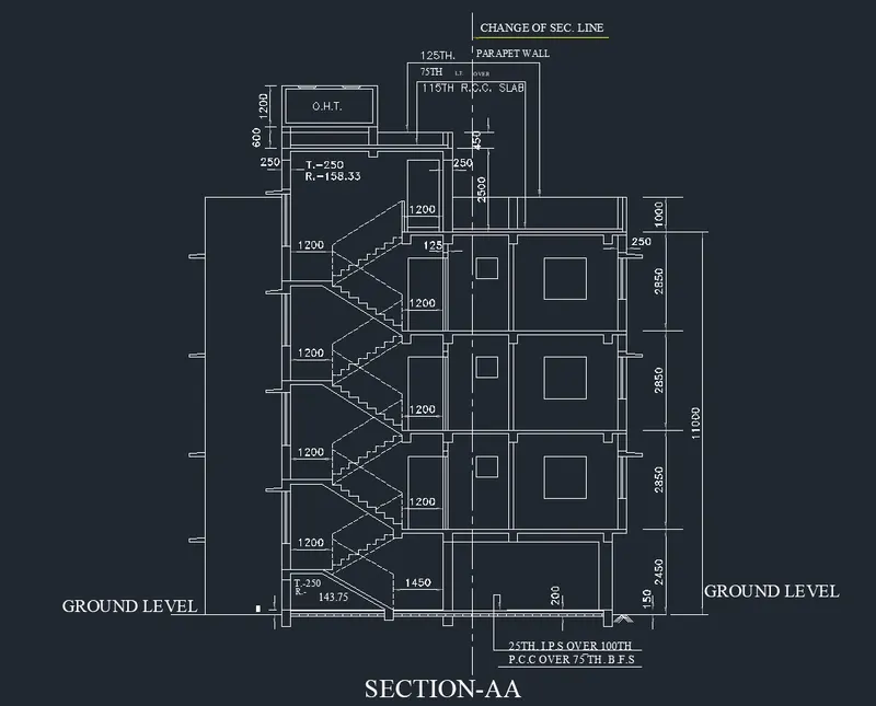
- The given figure -2 is about the elevation of that 3 storey building from section-AA along with steps from the ground floorto terrace
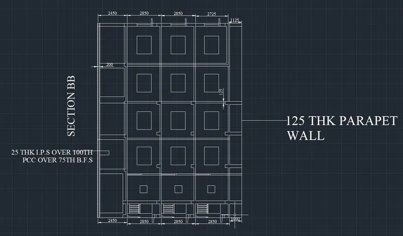
- figure -3 was about elevation from section-BB
- SECTIONS-AA
- To create the floor plan the total area of the plan should be drawn by using the ''line tool'' and ''rectangular tool''
- Then the walls and room sizes are separated by the offset tool with its required values
- The steps, doors, windows are created by the by referring the given dimension or by taking the standard sizes
- Steps are created the by using the array and tool from drawing the single line step line
- text are created the by using the ''mtext'' tool and copied for the multiple text required areas through copy tool
- The dimension are specified by using ''dimlinear''
- For lines with arrows the qleader tool was created
- SECTIONS -BB
- To create the elevation drawing we should take a reference of the floor plan drawing from section-BB
- Dimension of the windows and doors are directly taken from actual sizes of the floor plan dimension by line tool or xline
- If some of the dimension are cannot be done using reference then it can be done individually using offset tool or line tool
- The text are created by using the ''MTEXT'' tool and copied for multiple text
- Dimension are specified using ''DIMLINAR''
- For lines and arrows ''qleader'' is used