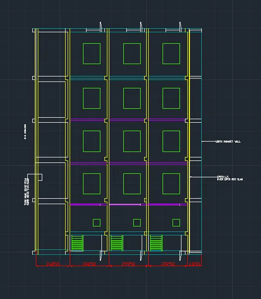
Creating a Layout, Section and Elevation with dimensions using AutoCad
Aim : To draw - (a) Plan (b) Section (c) Dimensioning
Procedure :
- Commands used :
1. Dimension - Command "DIM".
- To edit dimension style, text, etc. command "D"
- To move the dimension line select the grip point and move
- If we place the mouse on grip points of extension lines, we can see options such as stretch, continue dimension baseline dimension, and flip arrow.
- If we need to move or change the text's position, right-click the text's grip point: stretch, move with the dim line, move text only, move with the leader, above the dim line, center vertically, reset text position.
- Command "DIMEDIT" is used to edit the dimension line, to make it oblique, rotate, and change it to default.
- For text justification, the justification tab is selected from the toolbar in annotate tab.
- Command "DIMBREAK" to break the overlapping dimensions.
- Command "DIMCONTINUE" to continue dimensioning.
2. Dimension Style - Command "DIMSTYLE".
- We can create our own dimension style from the "new" menu.
- In this all the lines included in dimension (extension line, dimension line), their properties (color, lineweight, etc.) can be changed, and we can suppress extension lines.
- In Symbols and Arrows, we can change the shape of the arrowhead, arrowhead size, center marks, breaksize, etc.
- In text we can set the height of the text, color, and style.
- In fit option, if there is no space to place text and arrows in extension lines, options can be selected whether either text or arrows or both text or arrows etc., text placement, overall scale adjustments (all the features of dimension lines i.e. arrows, text, etc. will change to be input scale accordingly).
- Primary units, we can select the unit format (decimal, engineering, architectural), precision, decimal, separator etc.
- In alternate units, we can set another unit other than the primary unit, then two units will be displayed in the units position is all managed here.
- In tolerance, we can set the tolerance level and how it should be displayed in the drawing.
3. Offset - Command "O"
4. Trim - Command "TR"
5. Line - Command "L"
6. Text - Command "TEXT"
7. Layer - Command "LAYER"
8. Match properties - Command "MATCHPROP"
9. Multileader - Command "MLEADER"
10. Rectangle - Command "REC"
- PROCEDURE :
- PLAN
i. DRAWING THE PLAN:
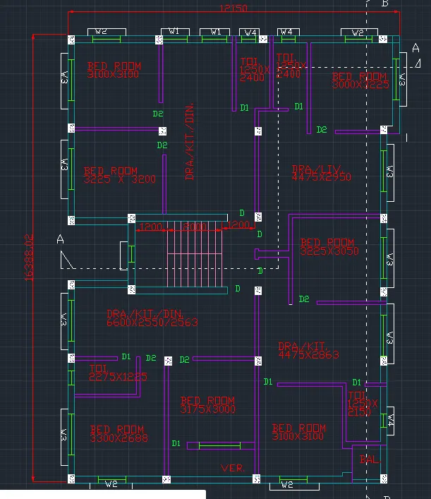
- Given outer wall thickness as 250mm and inner wall thickness as 125mm.
- Draw XL-H and XL-V, give the thickness of wall.
- Give the dimension of rooms Bedroom (3100x3100)mm by offset command.
- Give inner wall dimension as 125mm by offset method.
- Offset horizontally 2550mm, 125mm, 1250mm (toilet), 125mm, 125mm, 1250mm (Toilet of C), 3000mm (Bedroom of C), 250mm (external wall).
- Offset vertically 2400mm (toilet) and 125mm, 3225mm (bedroom of C), 125mm (wall thickness).
- Offset vertically 2950mm (drawing/living room) from bedroom of C and give wall thickness of 125mm, 3250mm and 3200mm give wall thickness of 250mm.
- Divide the rooms horizontally by offsetting 3225mm, 125mm, 3250mm, 125mm, 4475mm, 250mm.
- Offset 2400mm vertically and 4400mm horizontally for the staircase.
- Offset 3050mm vertically from drawing of C and 3225mm horizontally for the bedroom of B and offset the wall thickness also.
- Offset 3300mm vertically and 3100mm horizontally for the front bedroom.
- Fillet the wall of the bedroom with the left side wall and give wall thickness of 250mm.
- Offset 100mm from the outer wall, draw verandah by offsetting 1000mm and offset 3175mm for the bedroom of A.
- Offset 2888mm for the front bedroom of A and offset wall thickness of 125mm.
- Offset 1225mm and 2275mm for the toilet, then offset 2550mm for the drawing/kitchen/dining of A.
- Fillet all the corners and trim the excess lines.
ii. CREATING DOORS and WINDOWS:
- For the doors and windows following sizes are assumed:
- D - 1000 x 2100 mm
- D1 - 700 x 2100 mm
- D2 - 900 x 2100 mm
- W - 600 x 1200 mm
- W1 - 900 x 1200 mm
- W2 - 1000 x 1200 mm
- W3 - 1500 x 1200 mm
- Trim off the size of doors on the walls, wherever a door is required.
- Create windows of given sizes and place them in their respective places.
iii. TEXT:
- With multiline text, command "t" - create a text box, select standard as text style and text height as 250mm, and type the required text.
- Names of rooms with sizes and marking of windows and doors.
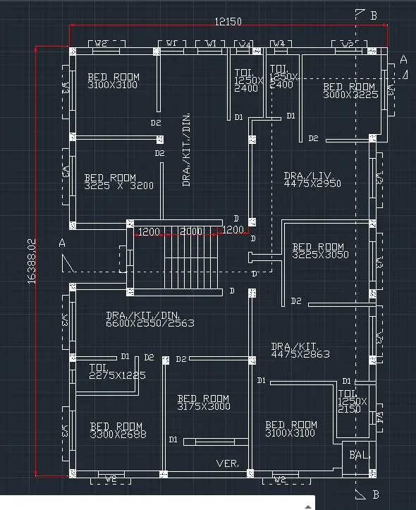
- 1st, 2nd, 3rd Floor plan.
- Scale 1:100.
- SECTION
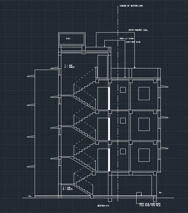
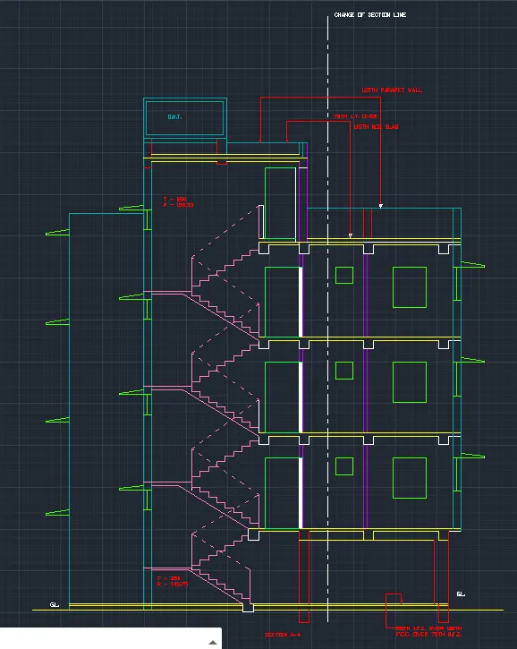
i. SECTION A-A:
- Assumed dimensions:
- Slab thickness - 100mm
- Beam - 300 x 350 mm
- Lintel level from floor - 2100 mm
- Lintel thickness - 150 mm
- Staircase waist slab thickness, landing slab thickness - 100 mm
- Height of newel post - 1000 mm
- Extend the wall thickness wherever the section cuts the plan.
- Then draw a horizontal line to show the ground level.
- Draw 150mm thickness from the ground level by offset command.
- Offset a distance of 2450mm from the ground level for the ground floor height.
- Give slab thickness of 100mm from the top level.
- Draw beams wherever the walls are there. Beam size of 300 x 350 mm.
- Draw columns of 400 x 300 mm width.
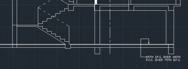
- DRAWING STAIRS:
- Draw a beam of 300mm width and 270mm depth down the ground level.
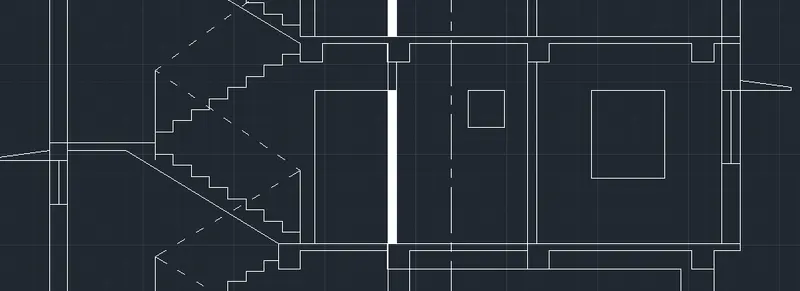
- At a distance of 1450mm from the 300mm column draw a vertical line of 143.75mm for the Riser (only till the First floor) and draw 250mm horizontal lines for Treads, then increase the riser size to 158.33mm for the above floors.
- Similarly draw 8 steps, draw the landing from the 8th one and offset a thickness of 100mm downwards.
- Draw an inclined line joining the riser end of the flight, offset 100mm from that line (waist slab), then join it with the landing slab.
- Mirror the steps to the opposite side meeting the next floor, given dotted lines as it won't be visible.
- Draw beam of 300 x 250mm as landing beam.
- Give the height of the newel post as 1000mm on both the start and end of the flight and connect it with an inclined line.
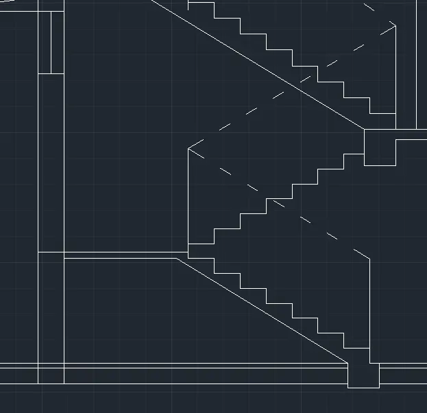
- For the first floor, offset a height of 2850mm, also give slab thickness of 100mm and the beam of 300 x 500mm.
- Extend the projected walls of 125mm and 250mm.
- Extend the doors and windows from the plan to get their width, then the height is given 1200mm for the window and 500mm for the ventilator.
- Draw lintel slab of 150mm and projection of shade as 400mm.
- Show section of the window on one end of the wall and the stair side as it is cut by the section line.
- Similarly copy the same on the respective floors, up to the 3rd floor.
- On top of the parapet give the height of 1000mm and 2500mm for the top room.
- Draw a door of 900 x 2100 mm door and wall thickness of 250mm on both sides.
- For the overhead water tank, draw a parapet height of 450mm.
- Extend the wall thickness and the beam.
- For the tank, draw a line of 1200mm as the height of the tank and 2300mm as the width of the tank.
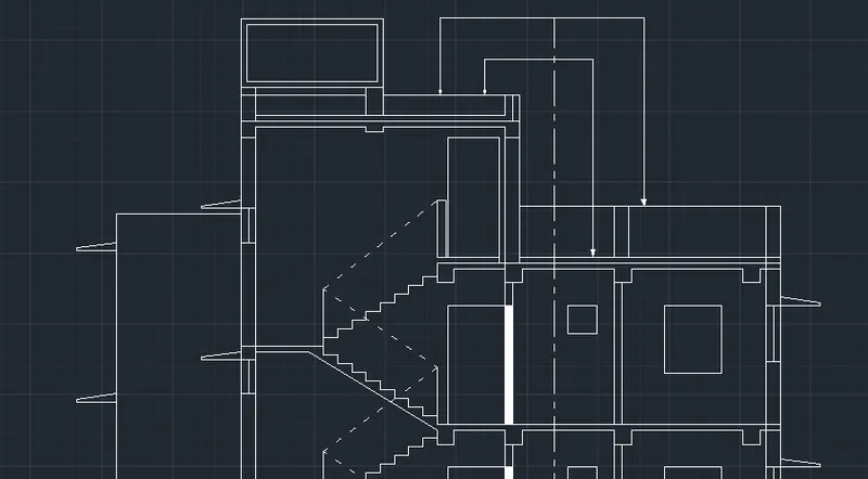
- With the use of multileader, text are written.
- Select leader from annotate tab - multileader style manager dialogue box displays.
- Create new - then give the ladder points as 5, text height as 100mm and arrow size as 100mm.
- Mark the parapet walls.
- TEXT:
- With multiline text, command "T" - create a text box, select standard as text style and text height as 250mm, type the required text.
- Tread and riser is mentioned, overhead water tank is marked.
ii. SECTION B-B:
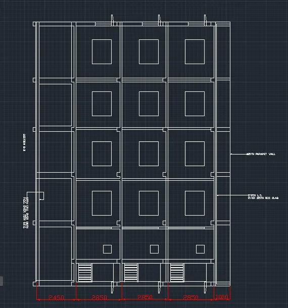
- Project the walls and columns from the plan using the line command.
- Mark a vertical line showing the Ground level, take an offset of 150mm for PCC and 200mm from the ground level to show the flooring level.
- Project the windows and ventilators and give the height 2100mm.
- Offset slab of 100mm thickness and draw the beams.
- Show the section of windows wherever the section line cuts the windows.
- With multileader, text size - 250mm and leader point as 2, write the text.
- LAYERS:
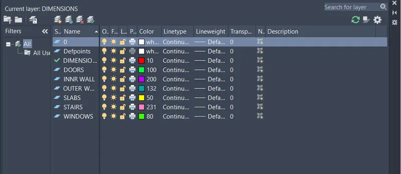
- Each component is placed in 7-layers.
- Layers for dimensions, inner walls, outer walls, doors, windows and ventilators, slabs, and stairs.
- RESULT:-
- PLAN:
- SECTION A-A:
- SECTION B-B: