Creating a Layout, Section and Elevation with dimensions using AutoCad
AIM : To Create the layoutplan ,section, and elevation by using autocad.
PROCEDURE :
- In this drawing we create a layout plan drawing using various commands.
- Now we can see the command used for this drawing as step by step.
Steps :
- We create a layoutdrawing given which consists of elevation , plan,and with section. so that we need to know the dimenssions clearly from figure given.
- first we need to create the plan with the help of lines to specified dimensions .
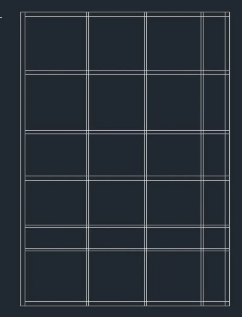
- Click " REC " for rectangle command used to outer of the plan.
- After that click " L " for line command to draw center lines
- Click " OF " for offset command to offset the line. and offset of outer wall is 250mm , for inner wall be 125mm.
- Create rooms as per dimenssions given using commands like line ,offset trim,extend etc...
- create a staircase with standard size for residential building.
- Also create layer properties witha different layer options.
- once plan is done den create drawings of section AA and section BB Along where it is mentioned in given figure.
- Click ' HAT ' for hatch command to hatch the point where needed.
- Then after doing section moving on to next create elevation of given plan.
- Click " DIM " for dimenssion and show the dimenssion.
- Also insert text with help of DTEXT command or single line text.
- Use the font names : Romans , Height : 8" and justify left.
- once everything is done using ' snipping tool ' take a screenshot & save the copy.
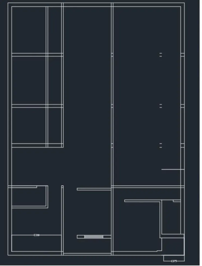
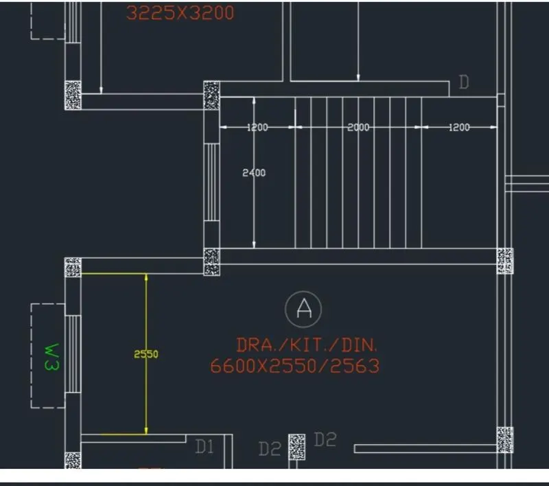
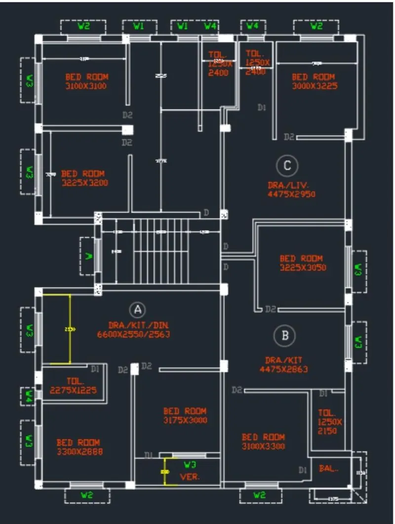
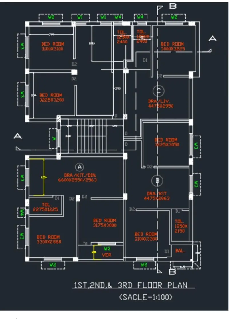
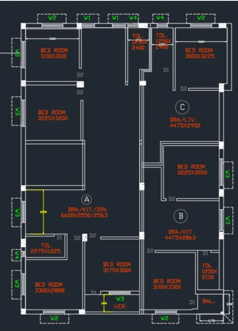
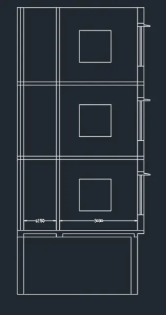
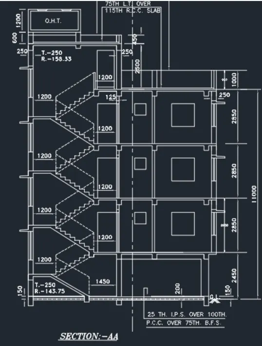
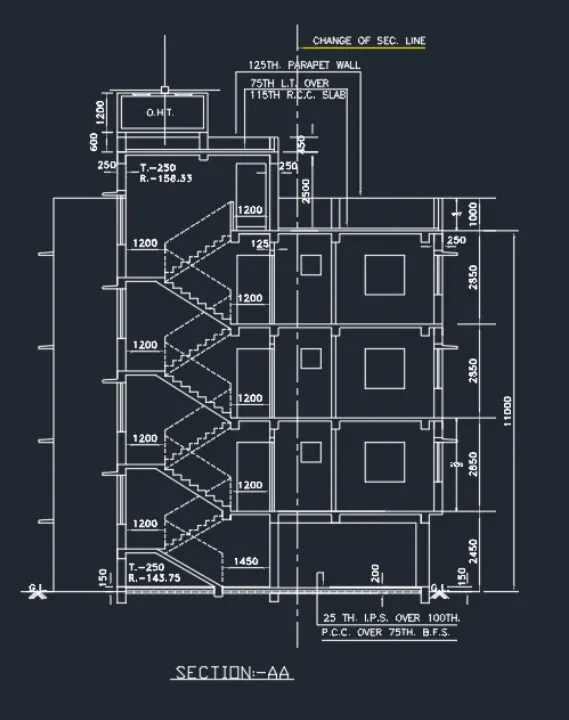
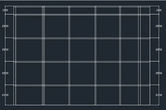
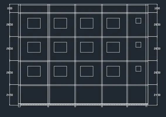
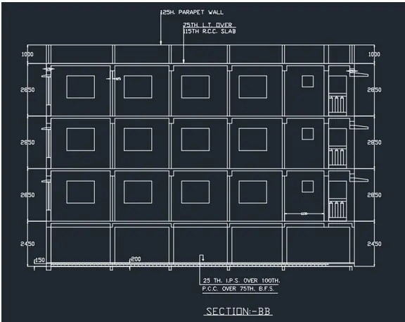
RESULTS : In this challenege we learned to create layout plan ,elevation , and section aling different direction and the figure which are drawn are shown in above figures.