Creating a Layout, Section and Elevation with dimensions using AutoCad
Aim:-
- plan
- section
- dimensioning
Procedure:-
commands used:-
1. Dimension:- command "dimlinear" fpr linear dimension
- to edit dimesion style ,text command "d"
- to move a dimension line select the grip point and move
- if we place mouse on grip points of extension lines, we can we options such as strech , continue , baseline dimension , flip arrow.
- command "dimbreak" is used to break the overlapping dimension
- commnad dimcontineous to continue dimensioning.
Dimension style : command "D"
- we can creat our own dimension style from new menu.
- In symbols and arrow , we can change shape of arrow head,arrow head sizes, centre marks, break size etc.
- in text , we can set height of text , colour , style.
2.multileader:-
To mark and write specification about the particular marked section multileader is used . more than one leader can be used at a time.
we can create oue won style of multileader , from annotate toolbar , manage multileader style is selected, then multileader style manager dialogue box appears.
3. offset- command "o"
4. Trim- commnad"tr"
5.line- command"l"
6.Text- command"t"
7. layer- command"layer"
8. Match properties:- command "matchprop"
Procedure:
1. Plan:
- Given outer wall thickness as 250mm and innear wall thickness as 125mm.
- Draw Xl-H and Xl-v give the thickness of wall.
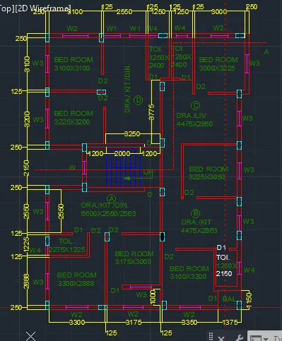
- Give the dimension of room bedroom 3100x3100 mm by offset command.
- give innear wall thickness as 125mm by offset method.
- offset horizontally 2550mm, 125mm,1250mm, 125mm,125mm,1250mm,(toilet),3000mm bedroom and 250mm external wall.
- Offset vertically 2950mm drawing room,from bedroom c and give wall thickness of 125mm,3250mm and 3200mm give wall thickness of 250mm.
- Divide the room horizontally by offseting 3225mm,125mm,3250mm,125mm,4475mm,250mm.
- offset 100mm from the outer wall, draw verandah by offseting 1000mm and offset 3175mm for the bedroom of A.
- offset 2888mm for the front bedroom of a and offset wall thickness of 125mm.
Creating doors and window:
D- 1000x2100mm
D1- 700x2100mm
D2-900x2100mm
W1- 900x1200mm
W2-1000x1200mm
W3- 1500X1200mm
W4- 500x500mm
W-600x1200mm
Text:-
With multiline text coomand "t" create text box , select standard as text style ans text height as 250mm type the require text.
Names of rooms with sizes and marking of window and doors.
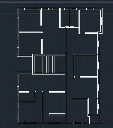
Each component are placed in layer 9 layer are created.
Layer for external wall, winddow , doors text, dimension , stairs, column slab and beam.
And, final result:
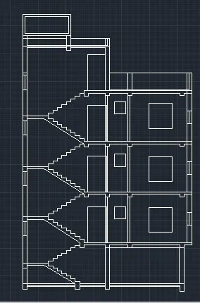
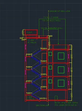
2. Sectin A-A:-
Assumed dimension:
slab thickness -100mm
Beam- 300x350mm
Lintel level from fioor-2100mm
Lintel thickness- 150mm
staircase waist slab thickness , landing slab thickness -100mm
Height of newel post- 1000mm
- offset a distance of 2450mm from the ground level for the ground floor height
- Give slab thicknes of 100mm from the top level
- Draw beams wherever the wall are there beam size of 300x350mm
- Draw columns of 400mm and 300mm width.
Drawing stair:
- Draw beam of 300mm and 270mm depth down the ground level
- At a distance 1450mm from the 300mm column draw vertical line of 143.75mm , expect the top floor 143.75mm
- Draw horizontal line of 250mm
- Similary draw 8 steps , draw the loading the 8th one and offset 100mm from that line, then joint it with the landing slab.
- mirror the step to the opposite side meeting
- Draw beam of 300x250mm as landing beam
- Give the height of newel post as 1000mm on both the start and fight,
For first floor , offset a height of 2850mm, also give slab thickness of 100mm and beam of 300x350mm.
Extend the projection wall of 125mm and 250mm.
Extend the doors and window from the plan to get its width.
Similary copy the same in respective floor , upto 2nd & 3 rd .
Text:
With multiline text coomand "t" create text box , select standard as text style ans text height as 250mm type the require text.
Names of rooms with sizes and marking of window and doors.
Layer:-
Each component are placed in layer 9 layer are created.
Layer for external wall, winddow , doors text, dimension , stairs, column slab and beam.
And, final result:-
:
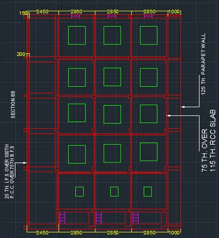
Section B-B:-
- Project the wall and column from the plan using line command
- Mark a vertical line showing ground level, offset of 150mm for p.c.c and 200mm from the ground level to show the floooring level.
- project the window and ventilators and give the height 2100mm
- offset slab of 100mm thickness and draw the beams
- Show the selection of window wherever the section line cuts the window
- With multileader , text size-250mm and leader point as 2, write the text
Dimensioning:-
command "dimlinear" fpr linear dimension
- to edit dimesion style ,text command "d"
- to move a dimension line select the grip point and move
- if we place mouse on grip points of extension lines, we can we options such as strech , continue , baseline dimension , flip arrow.
- command "dimbreak" is used to break the overlapping dimension
- commnad dimcontineous to continue dimensioning.
Dimension style : command "D"
- we can creat our own dimension style from new menu.
- In symbols and arrow , we can change shape of arrow head,arrow head sizes, centre marks, break size etc.
- in text , we can set height of text , colour , style.
Text:
With multiline text coomand "t" create text box , select standard as text style ans text height as 250mm type the require text.
Names of rooms with sizes and marking of window and doors.
Layer:-
Each component are placed in layer 9 layer are created.
Layer for external wall, winddow , doors text, dimension , stairs, column slab and beam.
And, final result:-