Creating a Layout, Section and Elevation with dimensions using AutoCad
1.
Aim
To create plan and section of the given figures. To use proper dimensions to the project. Also Assume size of Doors and Windows as per the standards.
Procedure
- Go to Auto Cad and use units commend to set the units as Decimal and precision as 0.
- Then set the limits of the drawing as 15000 in x axis and 15000 in Y axis.
- Then use line commend to draw lines
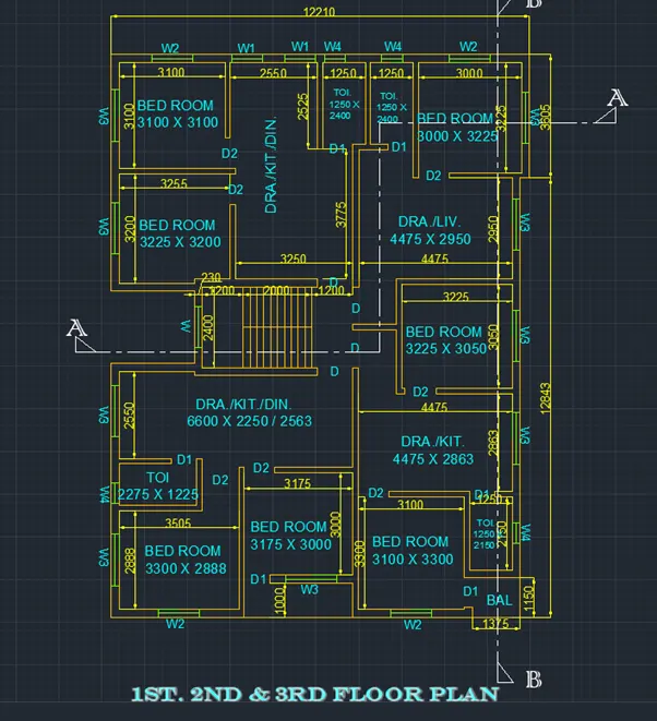
- And start sketching the plan as shown in the figure.
- Use offset commend to offset the outer line at appropriate distance.
- Then use fillet with radius of 0 to join the lines at the corner with 90 degrees.
- We can use layers by creating separate layers for walls, doors, windows, dimensions, text etc.
- Use different layer with different colours to customize the work.
- Then use trim commend to trim the excess lines in the plan.
- After drawing use annotate tab to provide dimensions.
- Type dim linear and click start point and then end point and place the dimension.
- Then dim continue and continue the dimension till necessary.
- Provide dimension where ever necessary by using same points.
- Provide text comment and type the required text.
- Then place the text at required place.
- Thus the Plan is prepared as shown in the figure.
- The same plan is repeated for 1st 2nd and 3rd
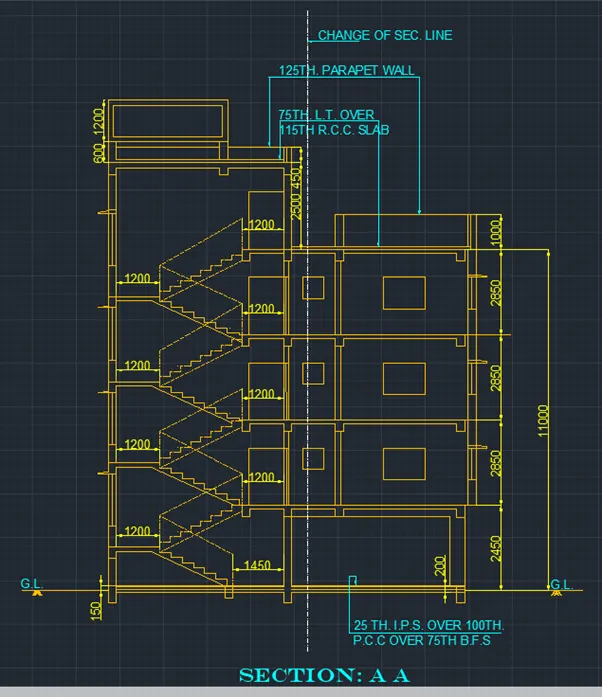
- After drawing the floor plan start section view of AA
- Use same line commend, offset commend, trim commend and annotations for creating the section.
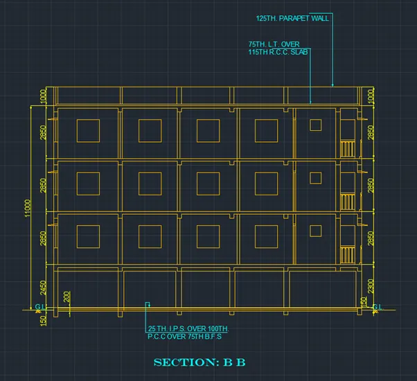
- After section AA create Section BB the section lines are drawn in the Plan itself.
- We can see the section view from the plan and draw a section.
- Thus the plan section AA and Section BB has been created.
Output
Result
Thus the Plan for 1st 2nd and 3rd floor and Section AA and section BB has been created by using AutoCAD Software. All the annotation and text has been done and the output has been presented.