Creating a Layout, Section and Elevation with dimensions using AutoCad
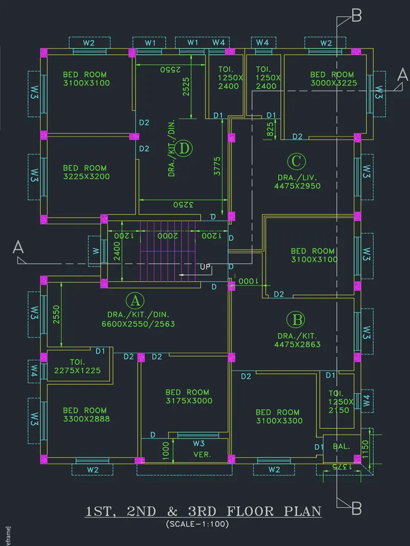
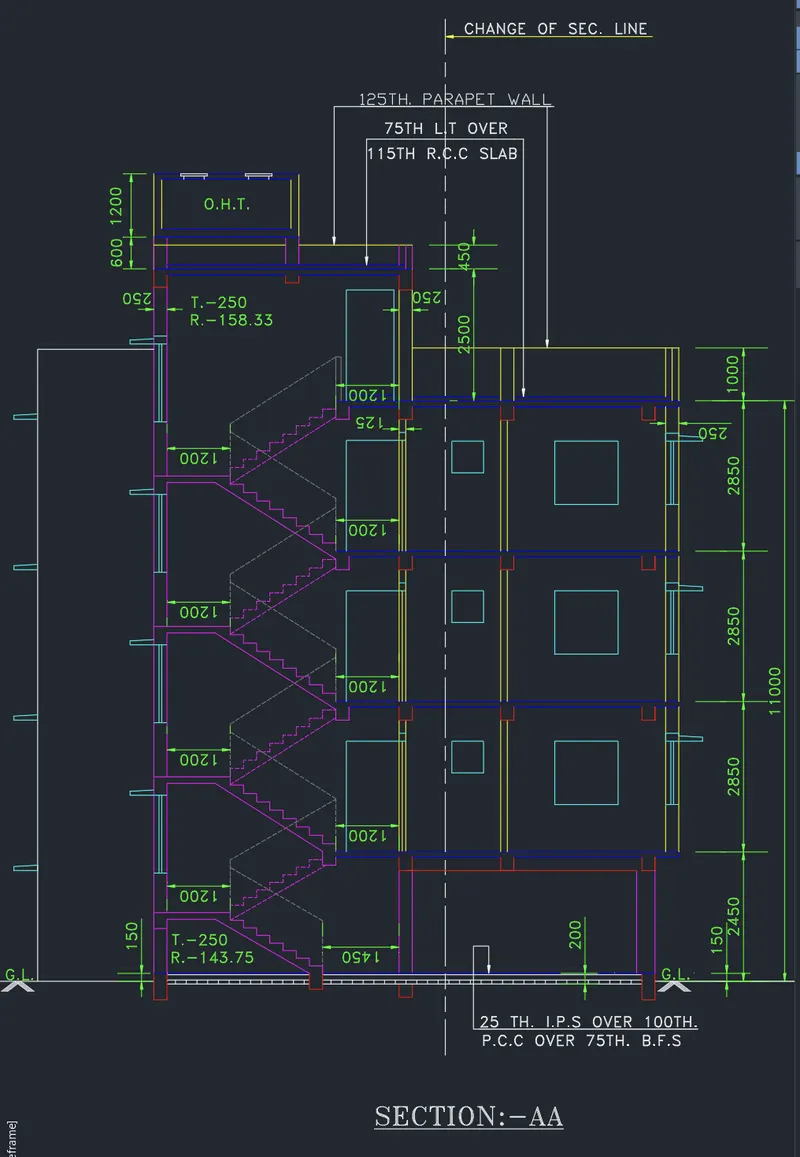
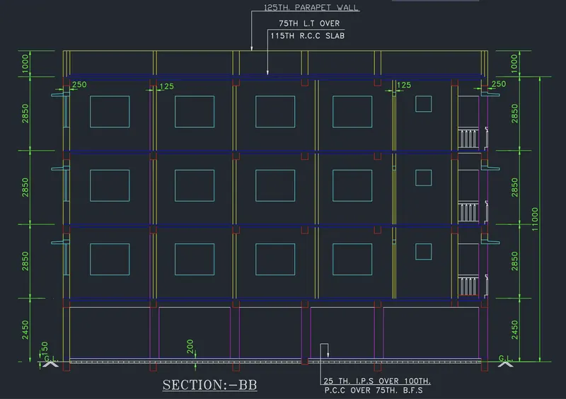
Question- Create the Plan and Sections as shown in the Figures. Use proper dimension techniques and dimension styles to document the project. Assume the sizes of the doors and windows as per construction standards. Refer to sections for stair details if required.
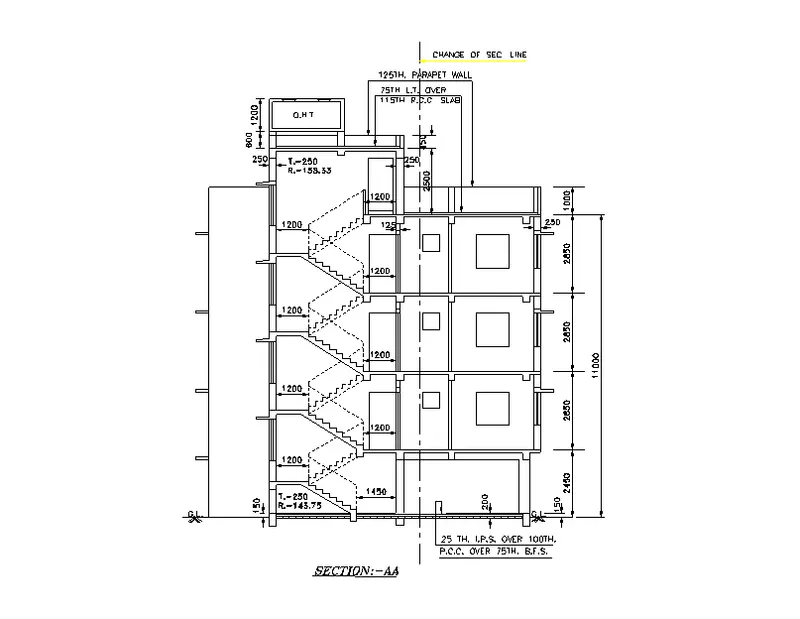
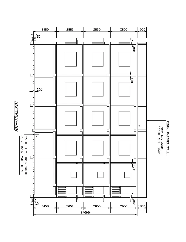
AIM:
To create layout plan, section & elevation by using AutoCAD with the help of given figure.
Introduction:
The plan, section & elevation is created in AutoCAD by using the tools like Draw, Modify, Annotation, Layer, Block and Properties. All the dimensions are in MM. The procedure of plan, section & elevation are explained in detail with figure and the final result is given.
Procedure:
STEP 1) Selection of Modal for Drawing
- Open AutoCAD
- STARTUP enter for new drawing
- Enter new value for startup 1 enter
- Create new file (a dialog box open)
- Go to last icon USE A WIZARD open
- Select ADVANCE SETUP click OK
- Select DECIMAL, precision 0>NEXT>NEXT>NEXT> NEXT>FINISH
- UN enter for unit setting
- Select DECIMAL, precision 0 in type
- Insertion scale select MILIMETER Click OK
- LIM enter for set limit
- Specify lower left corner 0,0 enter
- Specify upper right corner 30000,30000 enter
- Z enter for zoom
- Zoom for select ALL or A enter
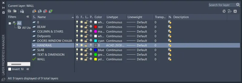
STEP 2) Assigned Layer Property
- RIBBON > LAYER PROPERTIES
- CREATE NEW LAYER > RENAME LAYER > WALL, DOOR, TEXT, STAIRS etc.
- Change colour for different layer
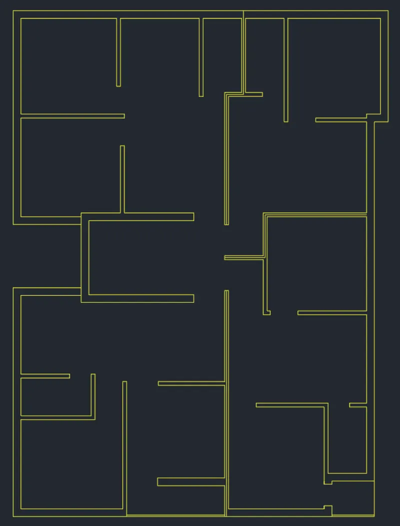
STEP 3) Sketching of Wall
- Set layer as WALL form layer property
- The drawing start with XLINE command
- Create two infinity line VERTICAL & HORIZONTAL which is intersecting each other
- TRIM lines as left down side from intersecting point
- Thickness of external wall is 250 and internal wall is 125
- OFFSET the lines as per given dimensions in drawing
- Partition the rooms by using TRIM and EXTEND command
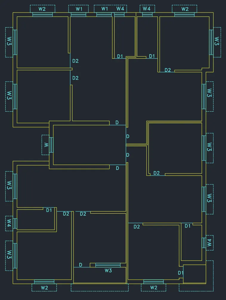
- For door opening use LINE, OFFSET, TRIM & ERASE command
STEP 4) Sketching Door, Window and Chajja
- Choose layer as a DOOR, WINDOW & CHAJJA
- Created window with the help of LINE, OFFSET, TRIM & ERASE command
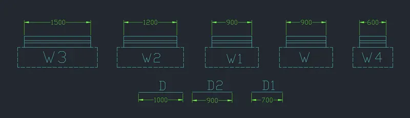
- Size of window for W=900, W1=900, W2=1200, W3=1500, W4=600 (assume)
- For chajja LINETYPE choose as an ISO dash with scale 8.000
- Create chajja with POLYLINE command
- Opening of door provide as for D=700, D1=900 & D2=1000 (assume)
- After creating door window converted it into BLOCK
- COPY as per required location as it given in drawing
STEP 5) Creating Column and Staircase
- Set as current layer for COLUMN AND STAIRS
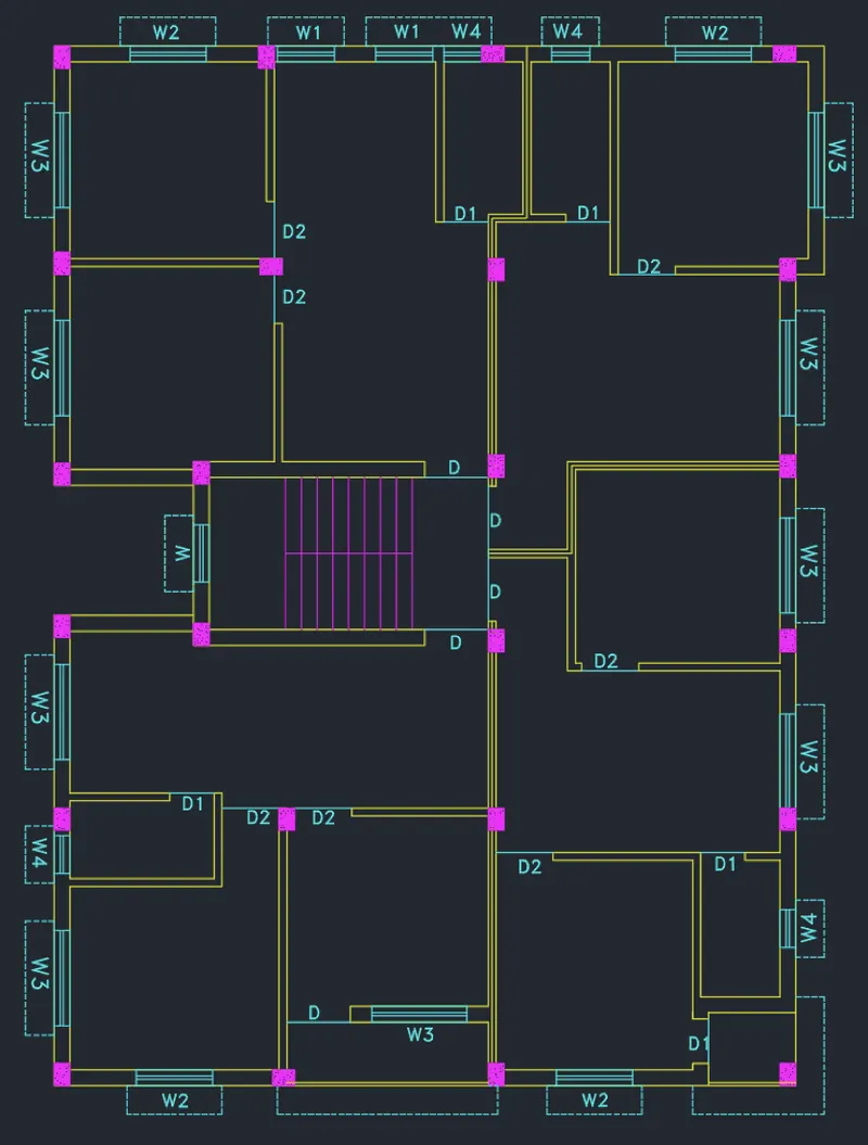
- Column created by entering command REC (rectangle)
- The size of rectangle as a column 250x350
- Hatching for column pattern AR-CONS with scale 0.1
- Staircase created by entering command O (offset)
- Offset as per dimension given in drawing
STEP 6) Text and Dimension Provided in Drawing
- Change layer as text and dimension
- Change font and height of the text from style text
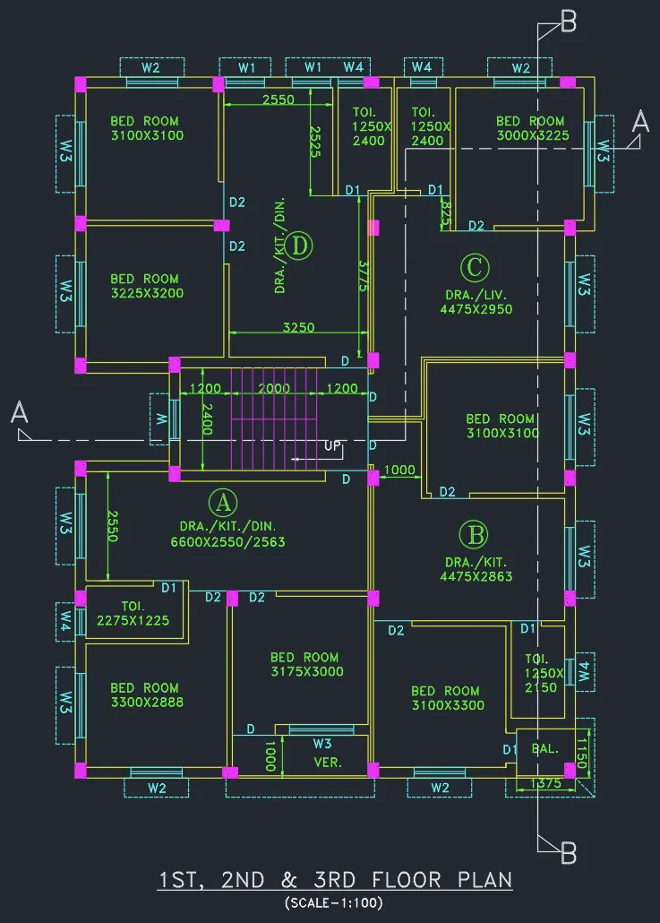
- Multi line text command used to specify the name for different room
- For dimensions, change arrow size as 5 from dimension style manager
- Specify the dimension as per shown in drawing
- Set layer as 0 for layer property
- Qleader command used to define the stair case direction and provide text
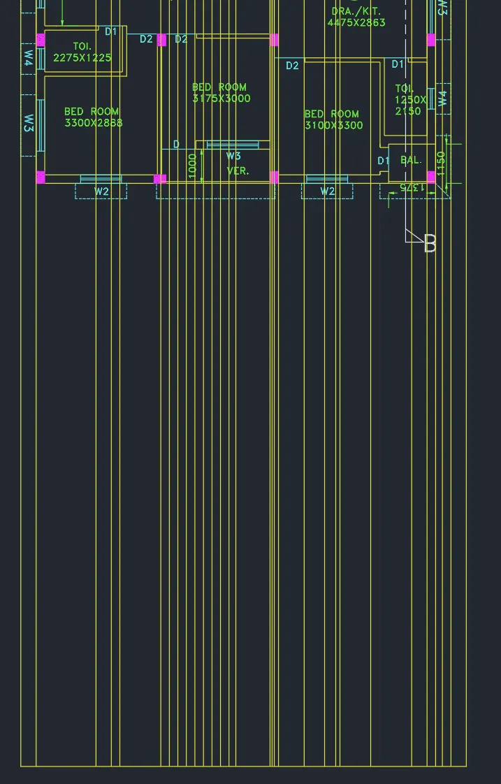
- Cut section A-A and B-B with line tool
- For section change linetype ISO long-dash double-short-dash and provide text
STEP 7) Section A-A Created for the Plan
- XLINE command help to draw an infinite line
- Horizontal line created below the plan
- Vertical lines created from the sections line in plan
- TRIM extra line which outside of the plan
- Through OFFSET command, create horizontal line as per required levels
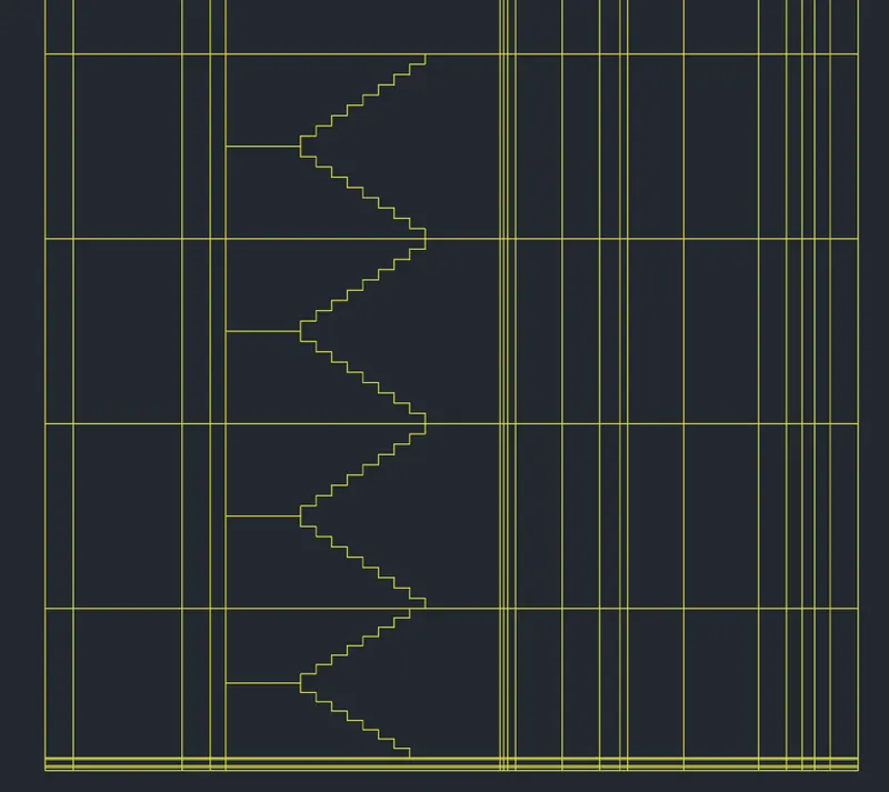
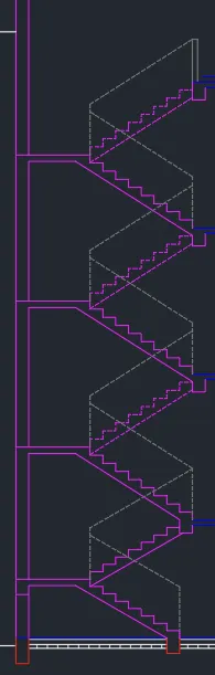
- Create staircase with the help of line, copy, trim, extend & mirror command
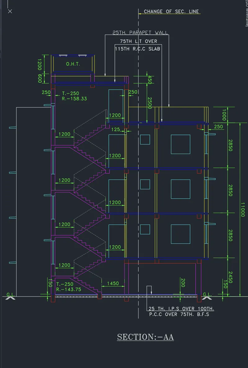
- Tread & riser for ground floor T=250, R=143.75
- 1st to terrace floor riser 158.33 and tread 250
- Waist slab thickness consider as 125
- 2nd flight of stair case set the linetype ISO dash and scale is 8
- Change layer as Handrail to create handrail for staircase
- After completing 1st floor stair case COPY for other floors
- Select the stair case section and set the layer as STAIRS AND COLUMN
- By using Offset command create a slab of 115 thickness at down side of floor level
- By using Line, Copy, Move, Erase, Trim, Extend command, create Door, window, chajja, overhead tank, parapet wall and Beam as per given size in drawing
- Specify the name by using Multi Line Text
- Use Dimension tool to show the measurement
- Multileader command used to show the direction and text
- Select object and specify the particular layers
STEP 8) Section B-B Created for the Plan
- Similarly, like section A-A created horizontal and vertical lines for section B-B by using XLINE command
- Trim unwanted lines which are outside of the drawing
- For creating window, chajja, slab, beam, wall and column used the commands such as line, offset, trim, extend, erase, copy and move
- Change layers according to member
- Created all required objects for ground & first floor, then select first floor to copy for other floors
- Specify the name by using Multi Line Text
- Use Dimension tool to show the measurement
- Multileader command used to show the direction and text
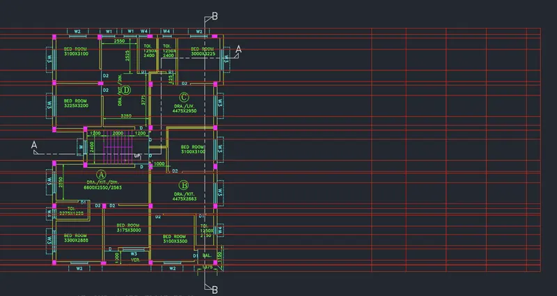
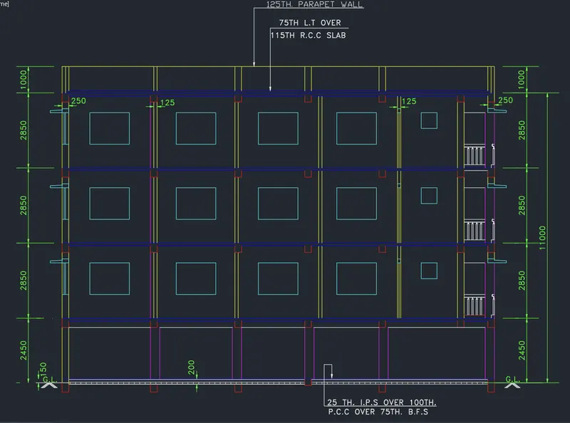
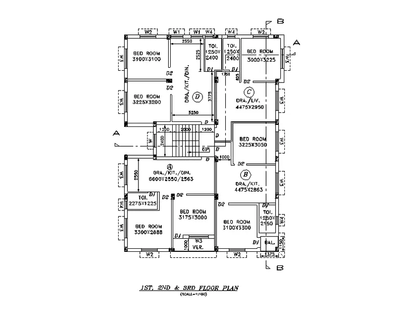
RESULT:
Following these step and procedure got final result as shown in figure