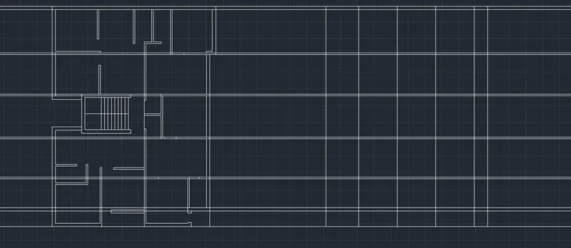
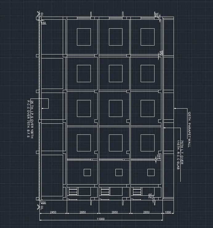
Creating a Layout, Section and Elevation with dimensions using AutoCad
Aim : To Create the Layout, Section and elevation with using the autocad
Introduction:
- The section shows the view of the structure as through it has been sliced in half or cut along another imaginary planes. This can be useful as it gives a view through the spaces and surrounding structure. typically across the vertical plane. that can reveal the relationship between the different parts of the buildings that might not be apparant on the plan drawing.
- Plan drawings are cut through the building on the horizontal plane. this usally shows the topview of the structure.
Commands used:
- unit command
- limit command
- zoom command
- line command
- Xline
- Offset
- Trim
- Block
- mirror
- copy
- move
- rotate
- scale
Procedure for drawing the plan:
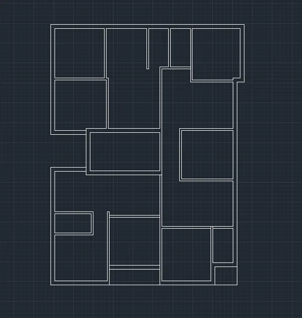
- Open new sheet enter the UN in thepromt box select the decimal and set the precision as 0.
- Select the xline command and draw the horizontal and vertical line.
- Select the offset and offset the vertical and horizontal line by 250mm.
- Offset the vertical line by 3300, 125.
- Offset the Horizontal line of the bedroom by 2888, 125, 1225, 125, 2550 and 250.
- Trim the unwanted lines.
- Offset the vertical line of toilet by 1225 and 125.
- Offset the vertical lione of bedrrom by 3175, 125, 3100, 125, 1250 and 250 ( the offset length is with respect to the last offseted line)
- Trim the unwanted lines.
- Offset the horizontal line of veranda by 1000, 250, 3000 and 125 and trim the all unwanted lines.
- offset the horizontal line of bedroom by 3300, 125, 2863, 125, and and balcony line by 1150, 250, 2150, 125 and trim the unwanted lines.
- Offset the bedroom horizontal line by 3050, 125, 2950, 125, 3225, 250 and trim the unwanted line.
- by using the fillet command join the top horizontal line and left side vertical line.
- offset the top left side bedroom vertical line by 3100, 125, 2550, 125, 1250, 125, 1250, 125, 3000 and 250.
- trim the unwanted lines.
- Offset the top left side bedroom horizontal line by 3100, 125, 3200, 250 and trim the unwanted lines.
- offset the horizontal line of the top toilet by 2400, 125 and extend these two lines upto next toilet and trim the unwanted lines.
- offset the top line of the DRA/KIT/DIN by 6300 downward and 230 mm and trim the unwanted lines.
- Offset the horizontal wall of the stair by 2400 downward and 230mm wall.
- offset the horizontal line of the DRA/KIT by 1200, 2000, 1200, 250 and trim the unwanted lines.
- for the drawing of the stairs ofsset tread of 250mm and landing is 1200mm.
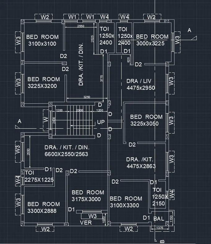
Sizes of the doors is assumed to be
D1 = 700 X 2100
D2 = 900 X 2100
D = 1000 X 2100
Sizes of the windows assumed to be
W1 = 1000 x 1200
W2 = 1200 x 1200
W3 = 1500 x 1200
W4 = 600x 600
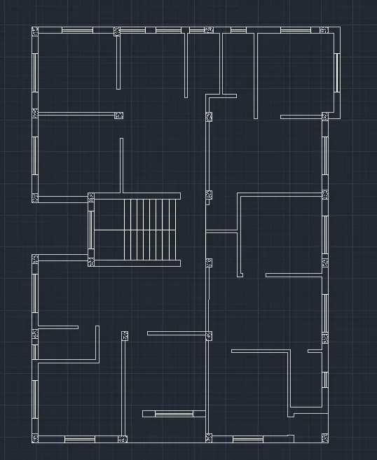
- The windows are drawn by using the line command and all are convertyed into the blocks and placed it where required.
- Columns are placed at required position and these columns are hatched.
- Enter DT and give the text and dimension is given by using the linear dimension.
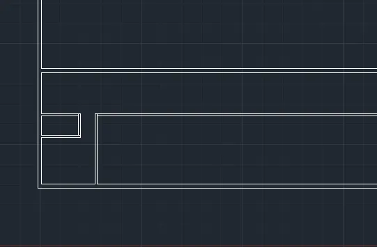
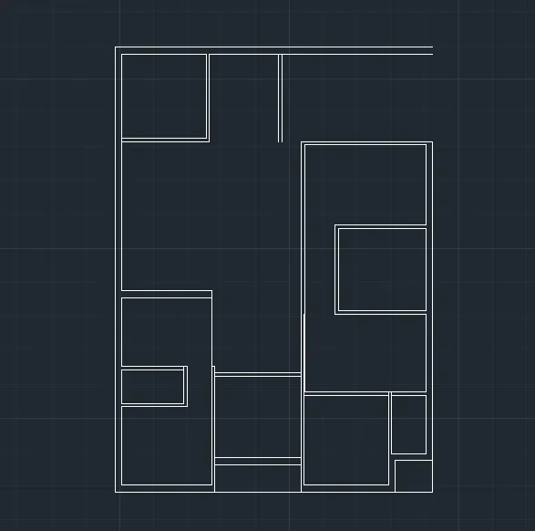
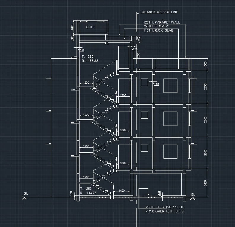
Procedure for drawing of section AA:
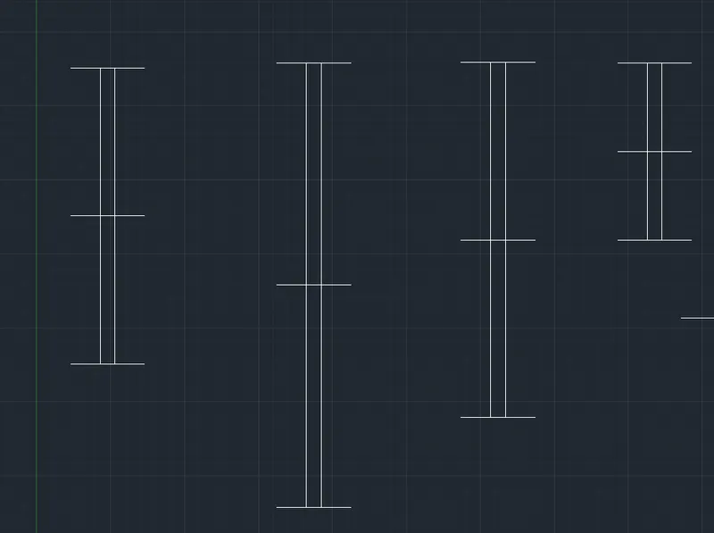
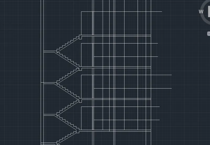
- By using the xline projects the lines from the plan in downward.
- Draw the GL line.
- From this line offset the 2450, 2850 1st floor, 2850 2nd floor and 2850 3rd floor and the 1000 parapet wall.
- trim the unwanted lines.
- For the drawing of the staircase offset the tread of 250mm and riser of 143.75 for the ground floor staircase.
- the starting of the first staircase is at 1450mm from the column surface and it ios drawn upto a landing.
- 1200mm landing is given and mirror the these staircase.
- for the first floor stair case is start at 1200 mm from the wall surface with a tread of 250mm and riser of 158.33mm. and drawn upto landing and mirror stair case.
- select the mirrored staircase lines and convert the linetype into ACADISO02W100.
- Convert this whole stair case as block and positioned at 2nd and 3rd floor.
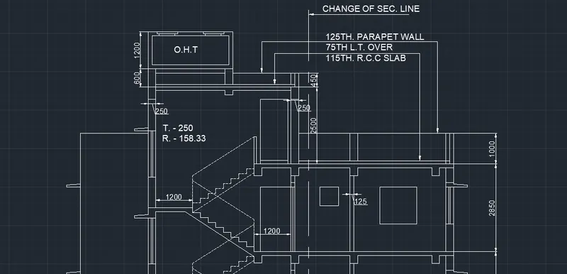
- offset the top floor slab surface by 2500 above and extend upto the stair wall and trim the line crossing the first wall surface offset the this line by 600 and 1200mm of OHT with width of 2750
- and offset this OHT lines inward by 115mm and by using the fillet command join them.
- door is drawn with width of 1000 and height of 2100 at the every floor. extend this lintel evel and this line is extended.
- offset this line with 1200below trim the all unwanted lines. and another window is by a 600mm and trim the unwanted lines. and the chejja is drawn.
- Offset the GL by 75mm below i.e BFS
- By using the single line command text are written
- by using the dimlinear dimensions are drawn.
Drawing of the section BB:
- From the plan Projects wall lines right side.
- Draw the base line as GL.
- Offset the Gl by a offset dstance of 2450, 2850, 2850, 2850 and 1000mm parapet wall.
- Offset the floor surface of 125mm left side at the very floor.
- Trim the unwanted lines.
- from plan projects windows line in right side.
- offset the floor level by right side of 2100mm and this line offset by 1200 left side. it done at the every floor. and chejja are drawn
- trim the all unwanted lines.
- beams are by using the line command.
- Offset the GL by 150mm right side and 50mm left side.
- by using the dimlinear the dimensions are given.
- By using the single line command the text are written.