Creating a Layout, Section and Elevation with dimensions using AutoCad
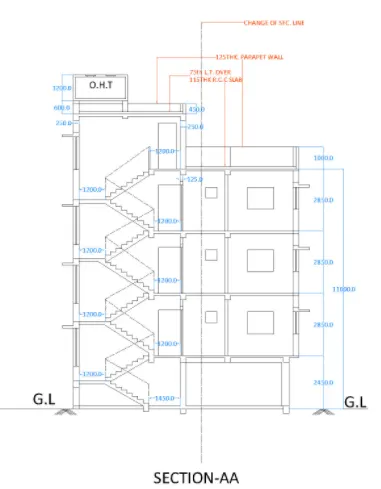
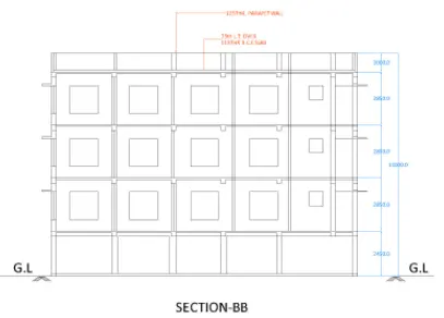
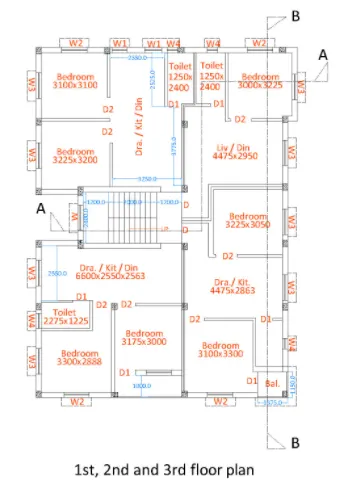
Aim :- Create the Plan and Sections as shown in the Figure into AutoCAD.
Introduction :- Create the Plan and Sections as shown in the Figures. Use proper dimension techniques and dimension styles to document the project. Assume the sizes of the doors and windows as per construction standards. Refer to sections for stair details if required.
Procedure :-
1st, 2nd and 3rd floor Plan
- The units are assigned to engineering precision in dwawing sheet
- Construction line in horizontal and vertical direction are drawn using the command XL-H and XL-V
- A corner is created by trimming the bottom & left side of the construction line using trim command :TRIM
- In order to create outer wall of 250mm thick, the offset of 250mm distance is given.The offset is created in horizontal and vertical direction
- Another offset of 125mm is created for inner walls
- Then an offset of the required room size is created from the innermost line in the vertical direction. An offset of 125mm is created for inner wall section. The extra lines are trimmed using trim command
- Similarly offset lines are craeted based on the size of room dimension given in the above plan
- In order to create the sections mentioned in the plan, constructions lines are drawn using approprite dimensions of rooms size and location of windows and doors are drawn
- Full plan is made using all deatiling included into the plan
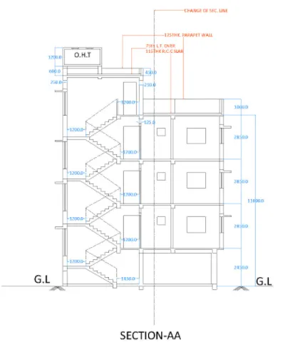
- Once the plan is drawn, the projection of plan are taken out at certain location of required section, the floors are created with using offset command with the appropriate floor height mentioned in the section
- The staircase is drawn using polyline command mentioning rise and thread given in the drawuing. For ground level, the riser = 143.75 mm and thread =250mm. And for the above floors athe riser= 158.33mm and thread =250mm. Support beam are provided giving offset to the staircase at floor level and at landing kevel.
- Trim out all the extra part, delete if lines are not trim
- The parapet wall and the over all head tank are drawn as per the dimensions mentioned in the drawing with the help of offset command
- Trim extra lines
- Similarly, project the projection of plan are taken out at certain location of required section, the floors are created with using offset command with the appropriate floor height mentioned in the section
- With all the projections obtained, the floor height is drawn and height is mentioned as per given in the above figure.
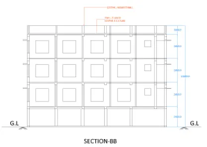
Result :- The drawing drawn is presented in the project contains the plan and two section of Three Storey Building. All the dimensions are given and all layers are assigned . The section lines are mentioned in the plan fo all better understanding of plan as well as sections.