Creating a Layout, Section and Elevation with dimensions using AutoCad
Q1:
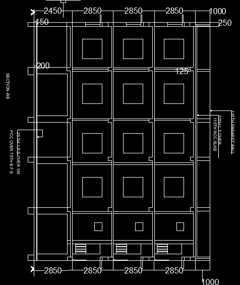
Aim: To create plan and sections as shown in the figure using AutoCAD.
Procedure:
In the command prompt type "UNITS" and press enter.
Select the units as "decimal" and insertion scale as "Millimeters".
Click ok.
Type "limits" in the command prompt and press enter.
Select "off" from the command prompt.
Type "Xline" in the command promp and press enter.
Type "v" and press enter.
Place the vertical xline anywhere in the workspace and press "esc".
Type "offset" in the command prompt and press enter.
Specify the off set distance as 230. and select the vertical line to offset.
Press "esc".
Type "Xline" in the command promp and press enter.
Type "H" and press enter.
Place the horizontal xline anywhere in the workspace and press "esc".
Type "offset" in the command prompt and press enter.
Specify the off set distance as 230. and select the horizontal line to offset.
Press "esc".
Press the spacebar two times to activate offset command and also to mention the distance.
Specify the required length to offset.
Repeat the same procedure as per required dimensions.
Type "trim" in the command prompt and press enter.
Select the lines to trim to get the required dimensions.
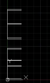
Type "offset" in the command prompt and press enter.
Specify the offset distance and press enter.
Select the lines to offset.
Press esc.
Again type "offset" in the command prompt.
Specify the offfset distance and press enter.
Specify the distance and press enter.
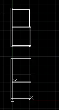
Select line tool from ribbon tab.
Specify the starting point as endpoint in the top line.
Draw the line in horizontal direction as per the dimension given in the figure.
Press esc.
Again use line tool from ribbon tab.
Draw vertical lines to indicate room partions.
Press esc.
Type offset in the command prompt and press enter.
Specify the offset distance for making internal walls.
Select the lines to offset.
Press esc.
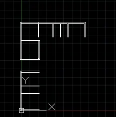
Select line tool from ribbon tab.
Specify the starting point as endpoint in the bottom line.
Draw the line in horizontal direction as per the dimension given in the figure.
Press esc.
Again use line tool from ribbon tab.
Draw vertical lines to indicate room partions.
Press esc.
Type offset in the command prompt and press enter.
Specify the offset distance for making internal walls.
Select the lines to offset.
Press esc.
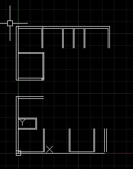
Select line tool from ribbon tab.
Sepcify the starting point as end point of previously created line.
Draw a horizontal line as per required length.
Draw a vertical line as per required dimensions.
Draw a horizontal line in negative xdirection as per required dimesnions.
Draw a vertical line in negative y direction as per required dimensions.
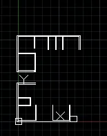
Select line tool from ribbon tab.
Sepcify the starting point as end point of previously created line.
Draw a vertical line as per required length.
Press esc.
Type offset in the command prompt and press enter.
Specify the distance and select the previously created line to offset.
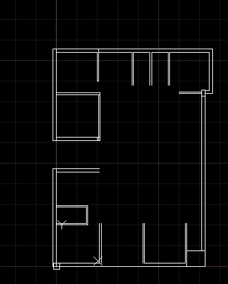
Select reactangle tool from ribbon tab.
Create the reactangle as per the dimensions and orientation required.
Selct the created rectangle and use move command.
Place the rectangle in the required posistions.
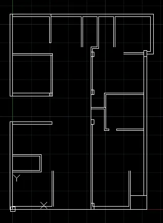
Select line tool from ribbon tab.
Draw horizontal line indicate the wall supporting stairs on both the sides.
Draw lines to specify riser.
Type offset command in the command prompt.
Specify the offset distance and select the lines to offset.
Press esc.
Select line tool from ribbon tab.
Draw lines to create windows and ventilators of required dimensions.
Create windows and ventilators in all the required places as per the given figure.
Click on the layer setting available on the ribbon tab.
Click create layer option, type the layer name as "dotted line".
Select the line type and click load.
From the list available, select the required linetype and click close.
Select the "set currrent layer" option and close the layer properties.
Now, select line tool from ribbon tab.
Draw the lines around windows to indicate sunshade.
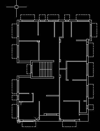
Again use rectangle tool from ribbon tab.
Create rectangle of suitable dimension and orientation.
Place the created rectangle using move command.
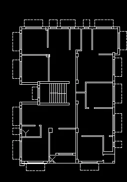
Select hatch tool from ribbon tab.
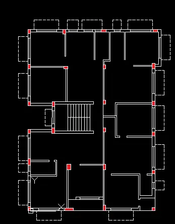
Selct solid fill from the hatch settings.
Select the required color.
Move the pointer to the column to give hatch.
Repeat the procedure to give hatch to all column markings.
Click on the layer setting available on the ribbon tab.
Click create layer option, type the layer name as "Section line".
Select the line type and click load.
From the list available, select the required linetype and click close.
Select the "set currrent layer" option and close the layer properties.
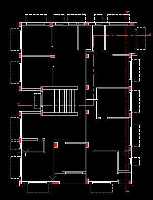
Now, select line tool from ribbon tab.
Draw the lines as given in the figure.
Click on the layer setting available on the ribbon tab.
Click create layer option, type the layer name as "dimension".
Select the line type and click load.
From the list available, select the required linetype and click close.
Select the suitable color
Select the "set currrent layer" option and close the layer properties.
Now, select dimlinear tool from ribbon tab.
Sprecify the starting and end point to display the dimensions.
Repeat the same dim linear tool to specify the dimensions.
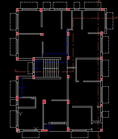
Select the text tool from ribbon tab.
Select "single line text".
Keep the cursor in the place where text has to start and click.
Type the required text.
Move the cursor to the next point where the text has to start and click.
Type the required text.
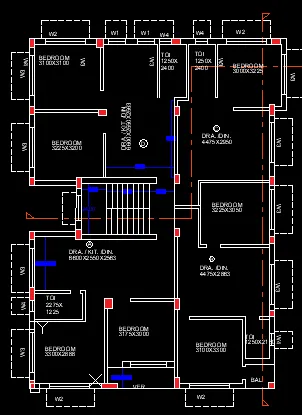
Select the all the text created in the previous step.
From the layer drop down list, select the dimension layer.
Now all the text created comes under dimension layer
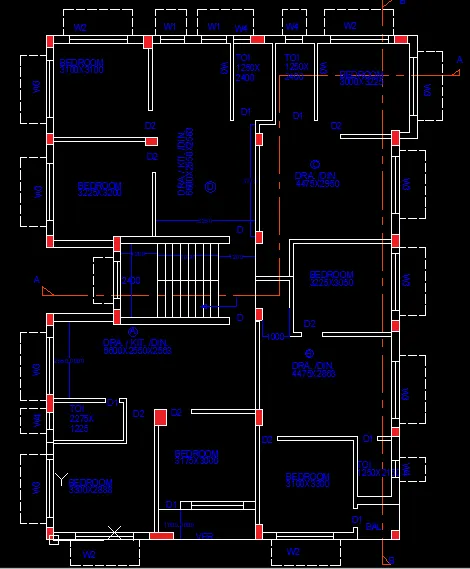
TO DRAW SECTION A-A
Select line tool from ribbon tab.
Draw a borizontal line as per the required dimension.
Again draw a vertical line as per the required dimension.
Draw a borizontal line as per the required dimension.
Select line tool from ribbon tab.
Draw a borizontal line as per the required dimension.
Again draw a vertical line as per the required dimension.
Draw a borizontal line as per the required dimension.
Type offset in the command prompt and press enter.
Specify the required distance to offset and select the object to offset.
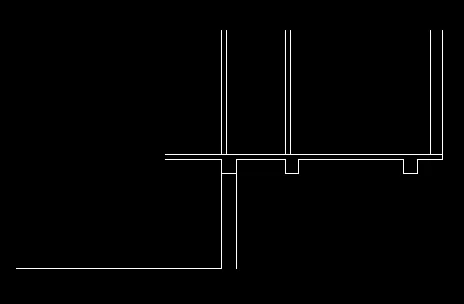
Select the rectangle tool from ribbon tab.
Create a rectangle of required dimension to indicate windows.
Place the cursor in the next point and create a rectangle to indicate ventilation.
Press "esc".
Use line tool from ribbon tab.
Draw the lines to create windows.
Use line tool from ribbon tab to draw sunshade.
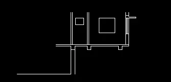
Select line tool from ribbon tab and specify the starting point.
Draw a line of suitable length indicating thread.
Again using line tool draw vertical line indicating riser.
Select the previously created riser and thread.
Type copy in the command prompt and press enter.
Select the suitable base point and press enter.
Place the copied place in the end point of riser.
Repeat the procedure to create stairs.
Use line command to create columns and floorings.
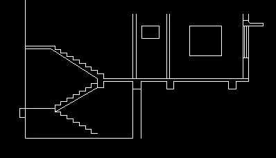
Use line tool from ribbon tab.
Draw vertial line in the recommended position.
Draw a horizontal line at both starting and end point of vertical line.
Press esc.
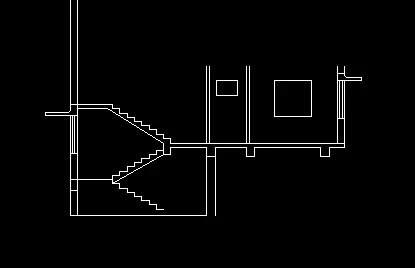
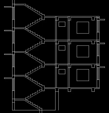
Select the previously created objects such as stairs, windows and floorings.
Type copy in the command prompt and press enter.
Select the suitable base point and move the copied objects in the vertical direction.
Place the in the required position.
Select the dotted line layer from the layer list.
Select the line tool from ribbon tab.
Daw a line to create hand railing.
Select the created railing and type copy in the command prompt, press enter.
Place the copied object in the suitable position.
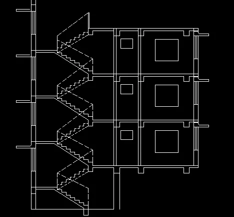
Select rectangle tool from ribbon tab.
Draw a rectangle indicating over head tank.
Press esc.
Type offset in the command prompt and press enter.
Specify the suitable offset distance.
Click on the object to offset.
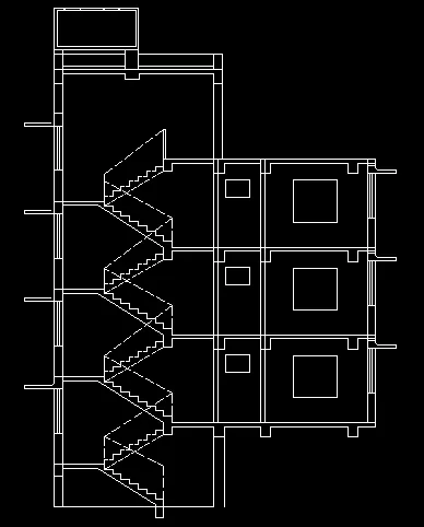
Select line tool from ribbon tab.
Specify the starting point near the endpoint of stair.
Draw a vertical line in the upward direction.
Draw a horizontal direction in right direction.
Draw a horizontal direction in downward direction.
Press esc.
Similarly use line command to draw other elements.
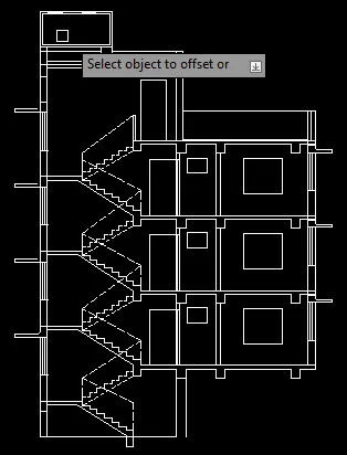
Select line tool from ribbon tab.
Specify the starting point as the bottom left corner point.
Draw a line negative x-direction.
Draw the next line in positive y-direction.
Draw the next line in positive x-direction.
Press esc.
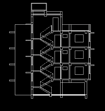
Click on the layer setting available on the ribbon tab.
Click create layer option, type the layer name as "dimension".
Select the line type and click load.
From the list available, select the required linetype and click close.
Select the suitable color
Select the "set currrent layer" option and close the layer properties.
Now, select dimlinear tool from ribbon tab.
Sprecify the starting and end point to display the dimensions.
Repeat the same dim linear tool to specify the dimensions.
Select the text tool from ribbon tab.
Select "single line text".
Keep the cursor in the place where text has to start and click.
Type the required text.
Move the cursor to the next point where the text has to start and click.
Type the required text.
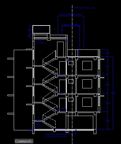
TO DRAW SECTION B-B
Type Xline in the command prompt and press enter.
Type H in the command prompt.
Place the horizontal xlines over the walls.
Press esc.
Select line tool from ribbon tab and press enter.
Draw a vertical line of required length.
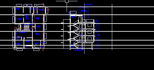
Type offset in the command prompt and press enter.
By refering to the plan specify the offset distance.
Select the vertical line to offset.
Type offset in the command prompt and press enter.
By refering to the plan specify the offset distance.
Select the vertical line to offset.
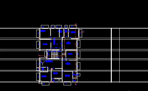
Select line tool from ribbon tab.
Draw line in positive x direction.
Press esc.
Type offset in the command prompt and press enter.
Specify the offset distance
Click on the line to offset.
repeat the same procedure to create the figure as required.
Select the previously created object using cursor.
Type copy in the command prompt and press enter.
Select the top corner as base point.
Move the copied objects in the positive x-direction.
Place the copied object at the required distance.
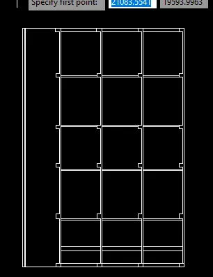
Select line tool from ribbon tab.
Draw line in positive x direction.
Press esc.
Type offset in the command prompt and press enter.
Specify the offset distance
Click on the line to offset.
Repeat the same procedure to create the figure as required.
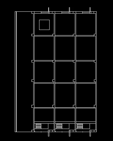
Select rectangle tool from ribbon tab.
specify the starting point.
Move the cursor to adjust the dimension.
Select the previously created rectangle.
Type copy in the command prompt and press enter.
Specify the suitable base point.
Place the copied objects in the positive x-direction.
Press esc.
Type copy in the command prompt and press enter.
Specify the suitable base point.
Place the copied objects in the negative y-direction.
Press esc.
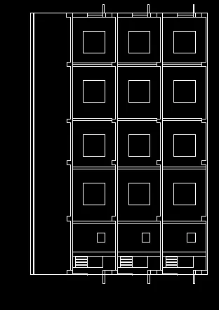
Select line tool from ribbon tab.
Specify the starting point at the botton
Draw a vertical line in negative x-direction.
type offset in the command prompt.
Specify the offset distance and press enter.
Select the previously created object to offset.
Repeat the same procedure as per the required dimensions given in the figure.
Press esc.
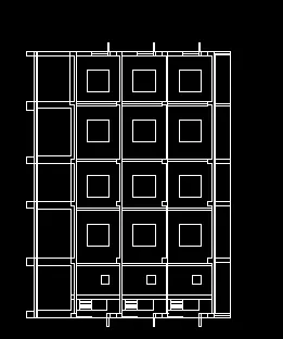
Click on the layer setting available on the ribbon tab.
Click create layer option, type the layer name as "dimension".
Select the line type and click load.
From the list available, select the required linetype and click close.
Select the suitable color
Select the "set currrent layer" option and close the layer properties.
Now, select dimlinear tool from ribbon tab.
Sprecify the starting and end point to display the dimensions.
Repeat the same dim linear tool to specify the dimensions.
Select the text tool from ribbon tab.
Select "single line text".
Keep the cursor in the place where text has to start and click.
Type the required text.
Move the cursor to the next point where the text has to start and click.
Type the required text.