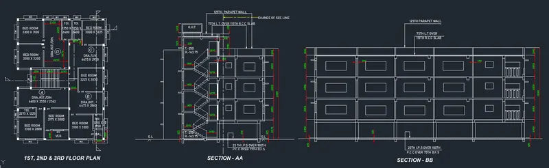
Creating a Layout, Section and Elevation with dimensions using AutoCad
LAYOUT, SECTIONS AND ELEVATION
1.
AIM:
To create the plan, sections and provide necessary dimensions to it, explain the procedure step by step to obtain the result.
INTRODUCTION:
AutoCAD is a computer aided design software and drafting software application.
In this project, i have used various commands like,
* Line,polyline - to create plan and sections.
* Dtext, Multi-leader - to mention the texts.
* Commands DIM Linear, DIM Continue - to create the Dimension lines.
* Hatch - in the ground level.
* Copy (Array) - to create objects.
* LAYERS - created individual layers for Plan and Sections, windows and doors, Dimensions, and texts.
* Fillet, Trim/erase, Offset, trim, ED - are regularly used at various places to complete the diagrams.
In the next step, the procedure is explained perfectly.
PROCEDURE:
- Open AutoCAD software
- Start from scratch
- Set the units to decimal and select ok
- Set limits as lower left corner (0,0) and upper right corner (1000,1000)
- Go to layer properties < create new layers < name the layers for reference < close
a.) Procedure for floor plan:
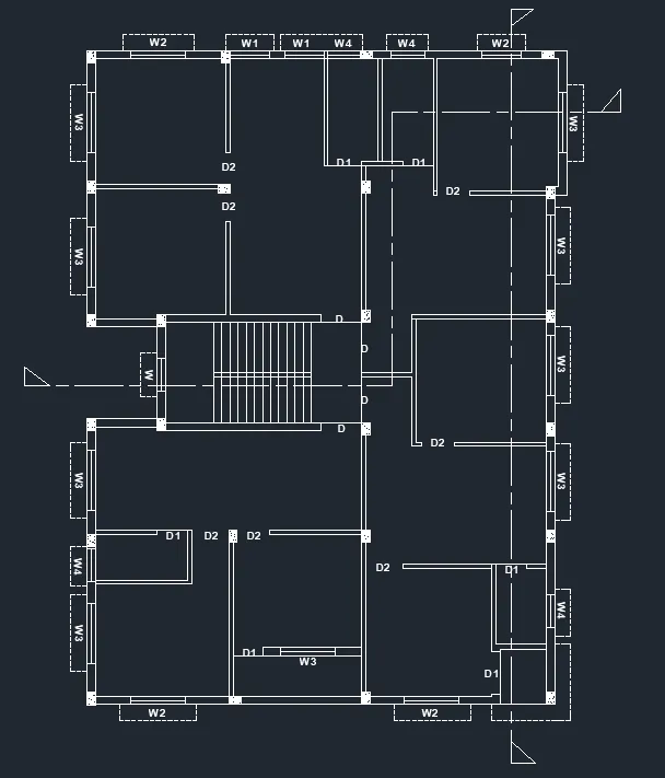
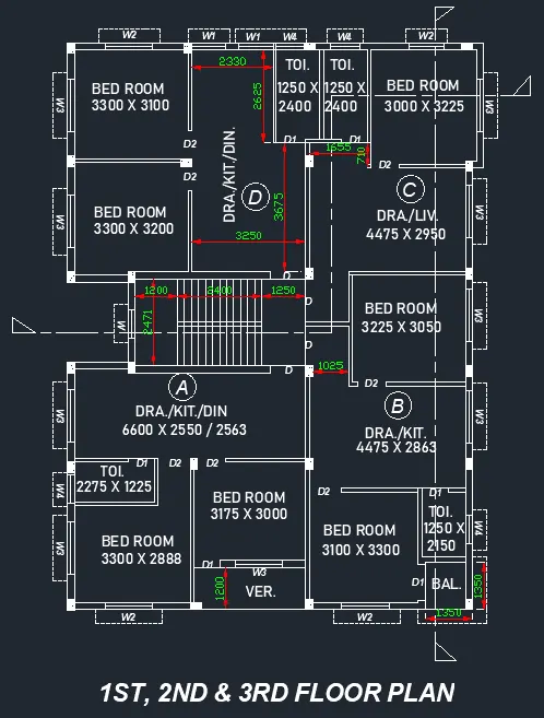
- Using the commands XLine(V and H), line, polyline, offset, fillet and trim, the floor plan is drawn as shown in figure.
- The following pictures show the step by step creation of floor plan.
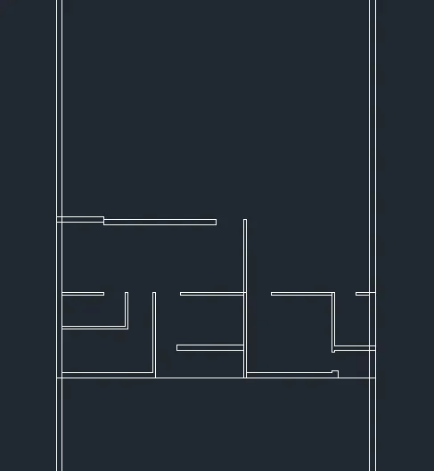
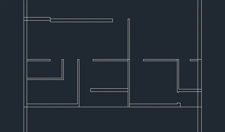
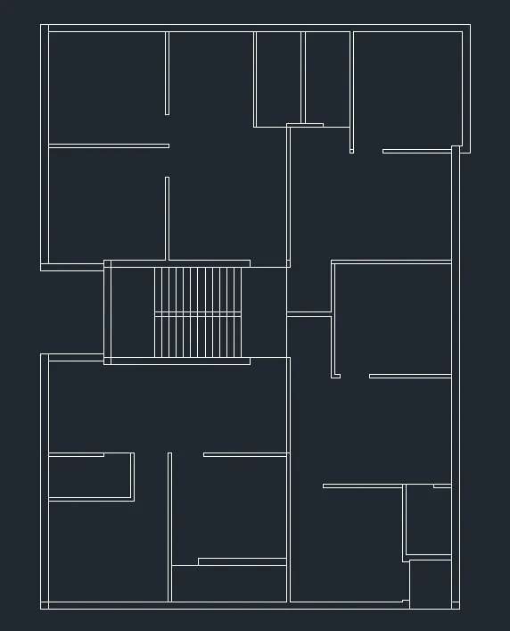
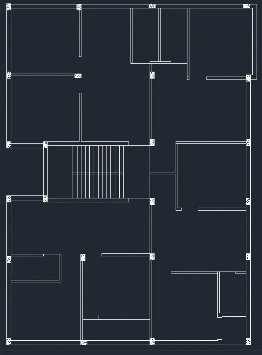
- The columns are drawn at places as shown in the figure and using the Hatch command (AR-CONC) the columns are filled up with the hatch and scaled up for better visibility.
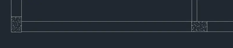
- Picture with all the columns drawn and hatched with AR-CONC.
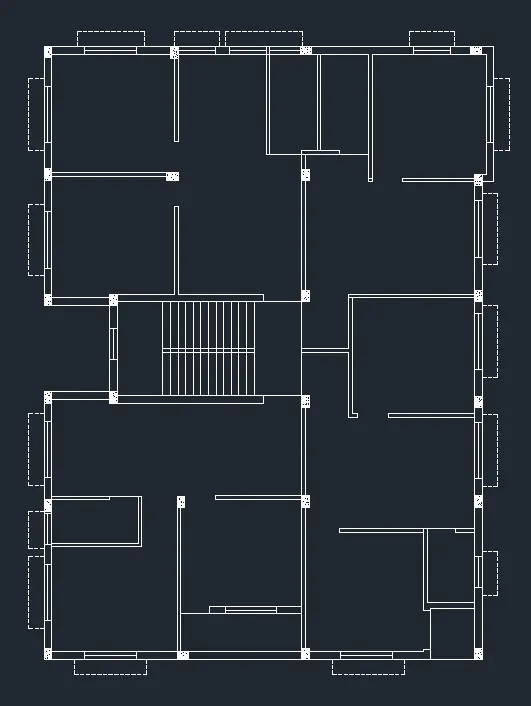
- In this step, I have created 4 different sizes of windows, sunshade using linetype SHORT-DASH and copy pasted it at the required places.
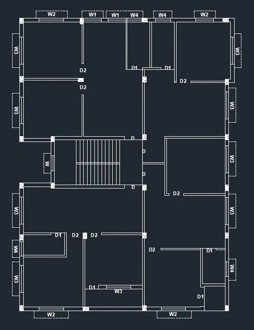
- Using DText Command, I have named the windows and doors and increased the text height for better visibility.
- Using the linetype, SHORT-DASH LONG-DASH the sections to be created is marked.
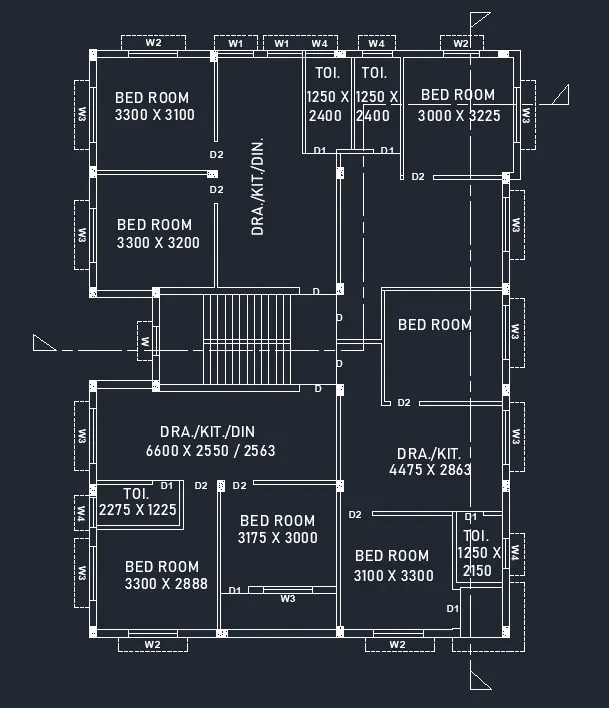
- Using the DText command, the room names and its dimensions are mentioned.
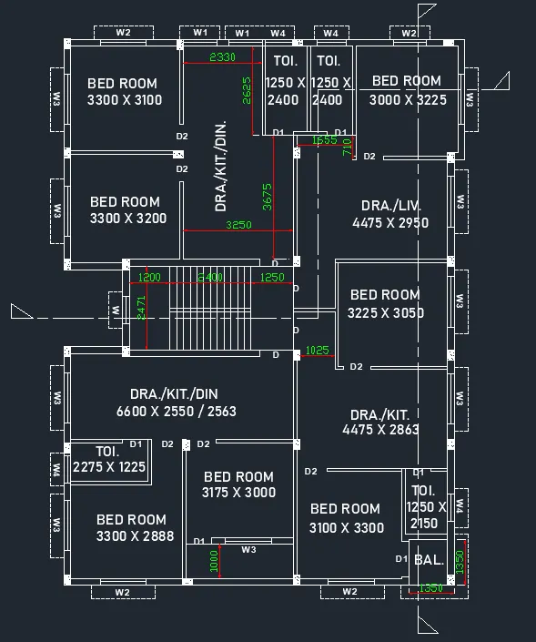
- Using the DIM LINEAR command, the dimensions are shown at required places and the colors for dimension lines and texts are changed for better viewing.
- Using the Command DText, I have created four alphabets A,B,C,and D.
- Then, Go to < Express tools < Choose Enclose in object < Select the four alphabets < provide the required scale < choose circle to enclose it < enter.
- Place the enclosed alphabets as shown in figure.
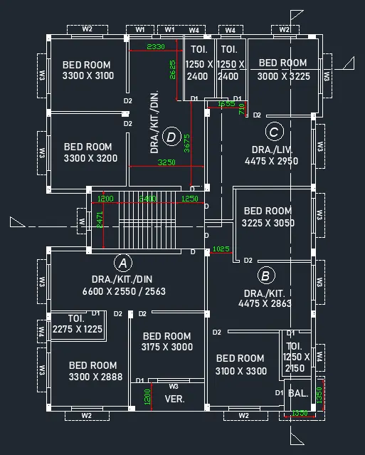
- Using the DText command, provide the title at the bottom.
a.) Result:
b.) Procedure:
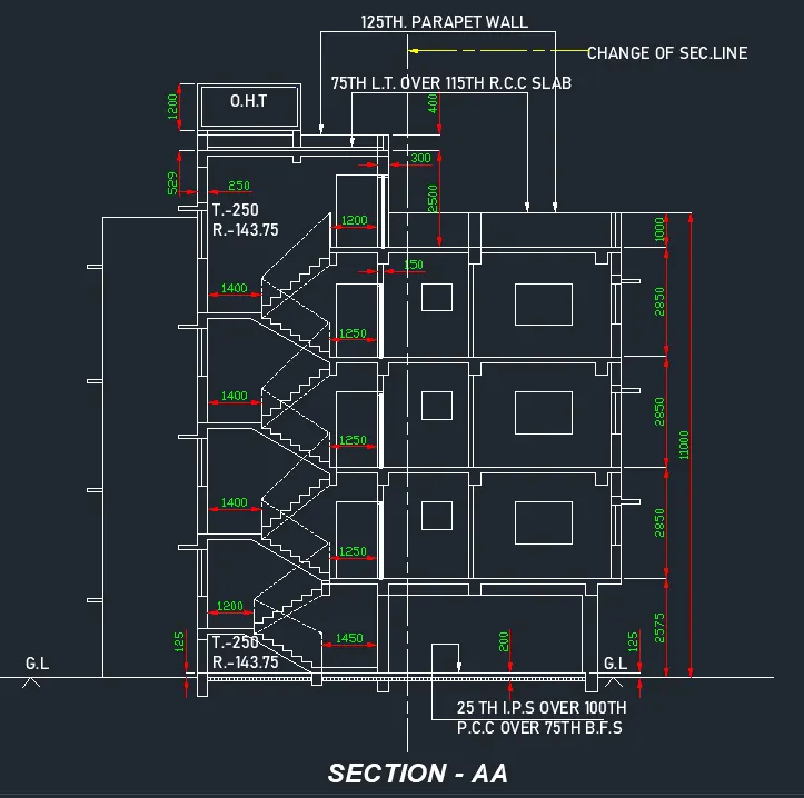
- Using the commands XLine(V and H), line, polyline, offset, fillet and trim, the section-AA is drawn as shown in figure.
- The following pictures show the step by step creation of section-AA.
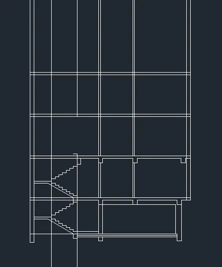
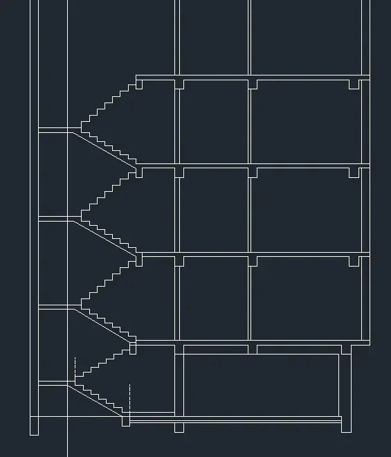
- Using the DIM LINEAR command, the dimensions are shown at required places and the colors for dimension lines and texts are changed for better viewing.
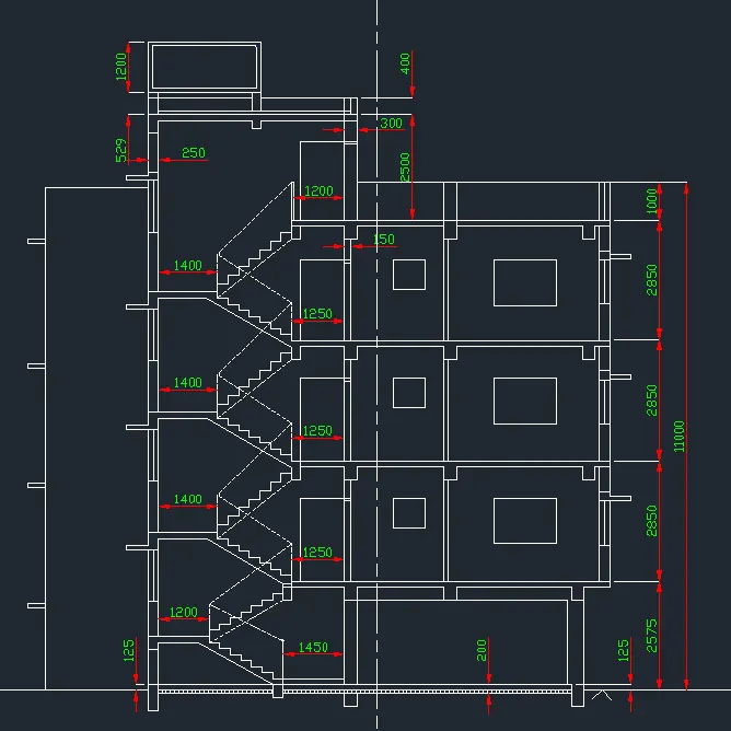
- Using the DText command, the texts are mentioned at required places as given in the figure.
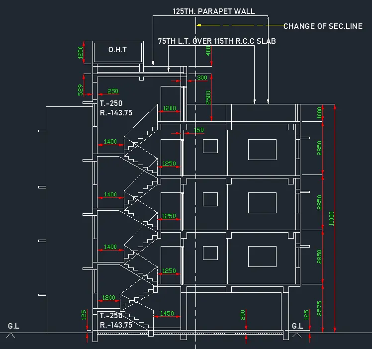
- Using the Multi-Leader command, the markings and the texts are mentioned as given in the figure.
- Using DText command, the title is mentioned in the bottom.
b.) Result:
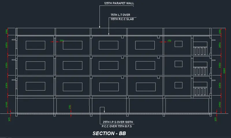
c.) Procedure:
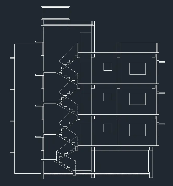
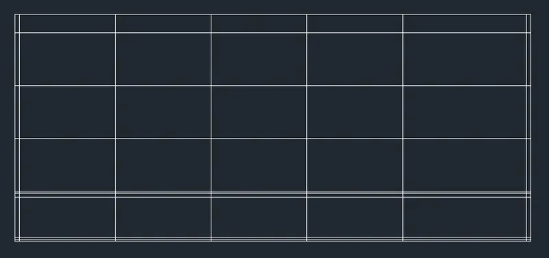
- Using the commands XLine(V and H), line, polyline, offset, fillet and trim, the section-BB is drawn as shown in figure.
- The following pictures show the step by step creation of section-BB.
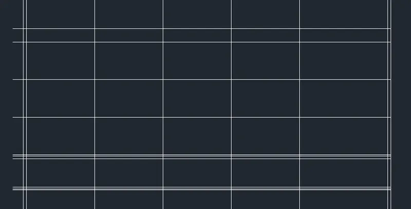
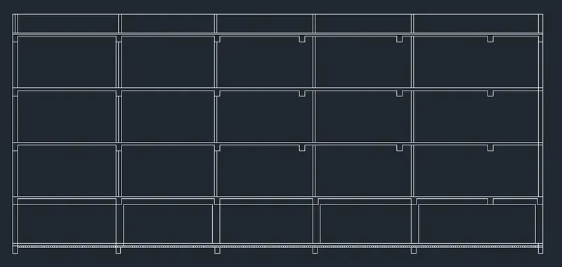
- The beams are drawn and shown in the following picture.
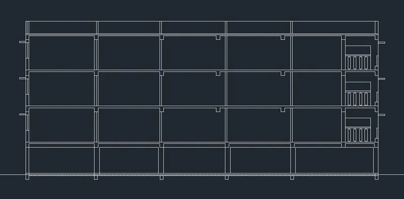
- The Balcony hand grills are drawn in the following picture.
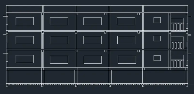
- The windows are drawn and copy pasted at required places.
- Using the DIM LINEAR command, the dimensions are shown at required places and the colors for dimension lines and texts are changed for better viewing.
- Using the Multi-Leader command, the markings and the texts are mentioned as given in the figure.
- Using DText command, the title is mentioned in the bottom.
C.) Result:
RESULT:
The final result with all the Diagrams,