Creating a Layout, Section and Elevation with dimensions using AutoCad
AIM: Create the Plan and Sections as shown in the Figures. Use proper dimension techniques and dimension styles to document the project. Assume the sizes of the doors and windows as per construction standards. Refer to sections for stair details if required
PROCEDURE:
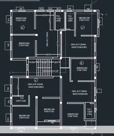
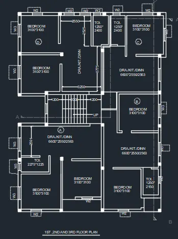
Figure 1 or floor plan of 1st,2nd and 3rd floor.
create a layer
draw rectangle of given dimensions use explode and offset command for walls
using fillet extend trim draw the floor plan
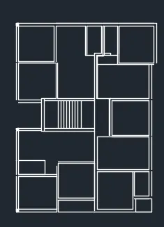
create a layer columns and draw columns and hatch it in every required place.
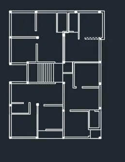
create a layer doors and windows and draw the required doors and windows using line command. and object snapp.
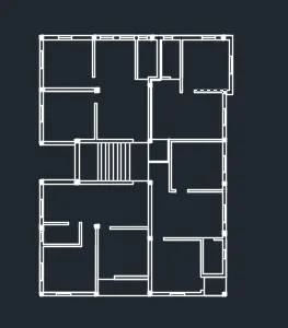
create a layer dimension and text and enter required text and dimension according to the drawing . from the dimstyle command set the arrow head of leader and dimline specifications . use dtext or mtext command to enter text and copy for many objects.
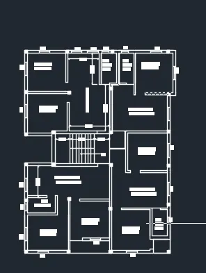
CREATE a layer grid and draw all the dotted lines. by setting line type as dotted line and transperacy 50
and grid mark BY selecting limetype as dotted line dash single dot and mark the lines A and B and name the drawing.
FOR FIGURE 2:
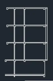
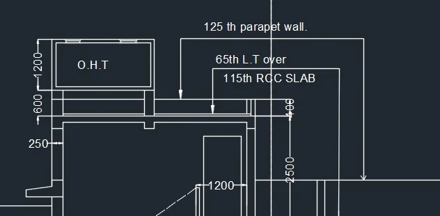
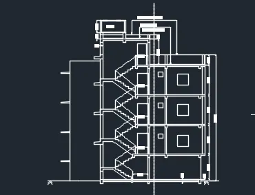
draw the part of the building walls with line , copy, trim and offset command. Assume the unknown sides.
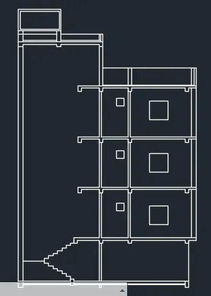
then draw the water tank and the stairs and outline of building.
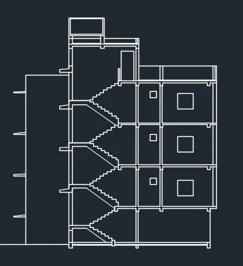
select the stairs to be dotted and match properties with the rest.
then add dimension and text in different layer.
FOR FIGURE 3:
Using line offset and copy command draw the elevation.
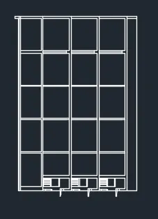
draw windows
then add text and dimension using dtextb and dimlin .
RESULT:
FOR FIGURE 1:
FOR FIGURE 2: