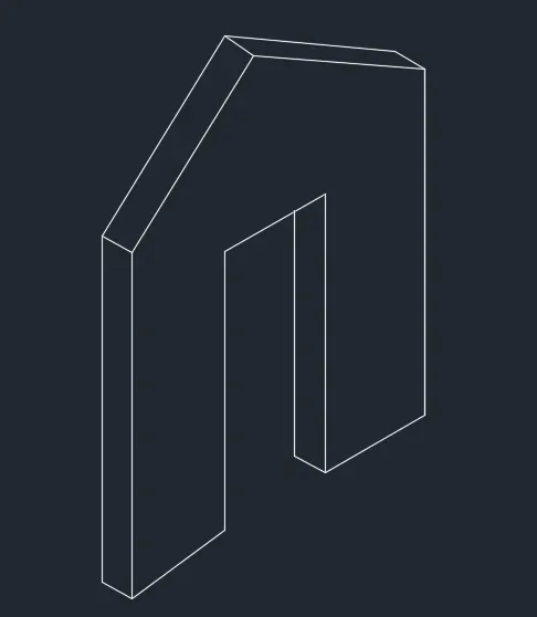
Creating a Floor plan, Footing detail and Isometric view using AutoCad
1.C-1
AIM:-
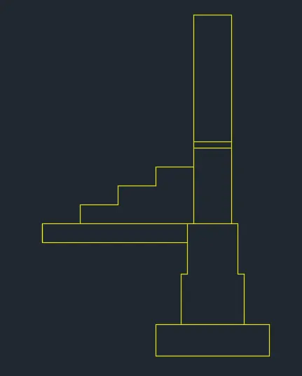
To create C.S of load bearing wall over spread footing.
Step by step procedure :-
- Command: UNITS
- Command: LIMITS
- Specify lower left corner (0,0)
- Specify upper right corner (420,297)
- Command: ZOOM
- Command: ALL
- Regenerating model
- Command: XLINE
- Specify a point: V
- Specify through point:
- Specify through point: cancel
- Command: offset
- Specify offset distance: T
- Select object to offset:
- Specify through point: 0.45
- Select object to offset:
- Specify through point: 0.45
- Select object to offset:
- Specify through point: 0.25
- Select object to offset:
- Specify through point: 0.25
- Select object to offset:
- Specify through point: 0.2
- Select object to offset:
- Specify through point: 0.2
- Select object to offset:
- Specify through point: 0.15
- Select object to offset:
- Specify through point: 0.15
- Select object to offset: Exit
- Command:XLINE
- Specify a point: H
- Specify through point:
- Specify through point: cancel
- Command: offset
- Specify offset distance: T
- Select object to offset:
- Specify through point: 0.25
- Select object to offset:
- Specify through point: 0.4
- Select object to offset:
- Specify through point: 0.4
- Select object to offset:
- Specify through point: 0.6
- Select object to offset:
- Specify through point: 0.05
- Select object to offset:
- Specify through point: 1
- Select object to offset: Exit
- Command: TRIM
- Select Cutting edges
- Select object :Select All
- Trim and Erase all the extra lines
- Command: LINE
- Specify first point:
- Specify next point : 1.15
- Specify next point :0.15
- Specify next point :1.15
- Specify next point :Cancel
- Command: JOIN
- Select souurce object: 1 found
- Select object to join: 1 found
- 2 line joined into 1 line
- Exit
- Command: XLINE
- Specify through point:
- Specify through point: cancel
- Command: offset
- Specify offset distance: 0.3
- Select object to offset:
- Select object to offset:
- Select object to offset:
- Select object to offset: Cancel
- Command: offset
- Specify offset distance: 0.15
- Select object to offset:
- Select object to offset:
- Select object to offset:
- Select object to offset: Cancel
- Command: TRIM
- Select Cutting edges
- Select object :Select All
- Trim and Erase all the extra lines
Result:
2.C-2
AIM:-
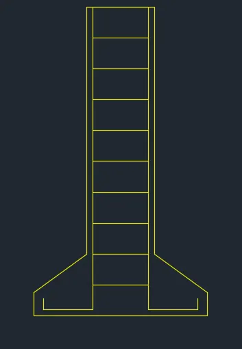
To create C.S Isolated footing using Auto Cad.
Step by step procedure :-
- Command: UNITS
- Command: LIMITS
- Specify lower left corner (0,0)
- Specify upper right corner (420,297)
- Command: ZOOM
- Command: ALL
- Regenerating model
- Command: XLINE
- Specify a point: V
- Specify through point:
- Specify through point: cancel
- Command: offset
- Specify offset distance: T
- Select object to offset:
- Specify through point: 0.08
- Select object to offset:
- Specify through point: 0.08
- Select object to offset:
- Specify through point: 0.12
- Select object to offset:
- Specify through point: 0.12
- Select object to offset: Exit
- Command:XLINE
- Specify a point: H
- Specify through point:
- Specify through point: cancel
- Command: offset
- Specify offset distance: T
- Select object to offset:
- Specify through point: 0.04
- Select object to offset:
- Specify through point: 0.15
- Select object to offset:
- Specify through point: 0.36
- Select object to offset:
- Specify through point: 1.6
- Select object to offset: Exit
- Command: TRIM
- Select Cutting edges
- Select object :Select All
- Trim and Erase all the extra lines
- Command: LINE
- Specify first point:
- Specify next point : 1.15
- Specify next point :0.15
- Specify next point :1.15
- Specify next point :Cancel
- Command: JOIN
- Select souurce object: 1 found
- Select object to join: 1 found
- 2 line joined into 1 line
- Exit
- Command: XLINE
- Specify through point:
- Specify through point: cancel
- Command: offset
- Specify offset distance: 0.3
- Select object to offset:
- Select object to offset:
- Select object to offset:
- Select object to offset: Cancel
- Command: offset
- Specify offset distance: 0.15
- Select object to offset:
- Select object to offset:
- Select object to offset:
- Select object to offset: Cancel
- Command: TRIM
- Select Cutting edges
- Select object :Select All
- Trim and Erase all the extra lines
- Command: offset
- Specify offset distance: 0.2
- Select object to offset:
- Select object to offset:
- Select object to offset:
- Select object to offset:
- Select object to offset:
- Select object to offset:
- Select object to offset:
- Select object to offset:
- Select object to offset:
- Select object to offset: Cancel
- Command: LINE
- Specify first point:
- Specify next point : 1
- Exit
- Command: offset
- Specify offset distance: 0.04
- Select object to offset:
- Command: TRIM
- Select Cutting edges
- Select object :Select All
- Trim and Erase the extra lines
- Command: LINE
- Specify first point:
- Specify next point :
- Exit
- Command: LINE
- Specify first point:
- Specify next point :
- Exit
Result:
3.C-3
AIM:-
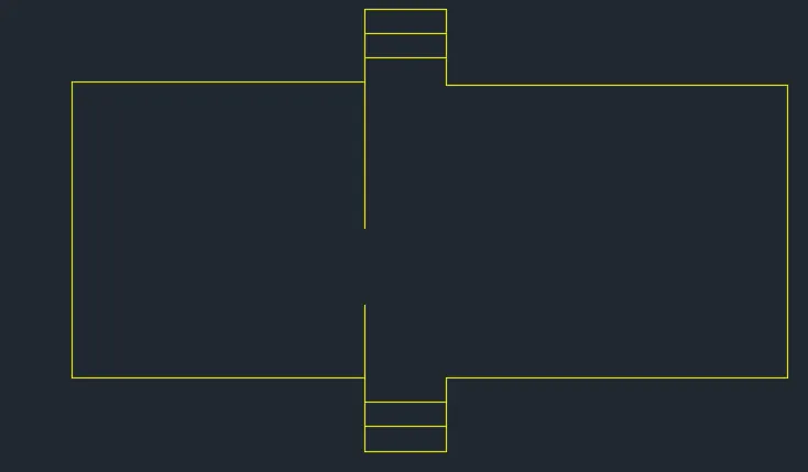
To create Line diagram of a two bedroom building using Auto Cad.
Step by step procedure :-
- Command: UNITS
- Command: LIMITS
- Specify lower left corner (0,0)
- Specify upper right corner (420,297)
- Command: ZOOM
- Command: ALL
- Regenerating model
- Command: PLINE
- Specify next point:3.6
- Specify next point:0.9
- Specify next point:1
- Specify next point:0.9
- Specify next point:4.2
- Specify next point:3.6
- Specify next point:4.2
- Specify next point:0.9
- Specify next point:1
- Specify next point:0.9
- Specify next point:3.6
- Specify next point:Close
- Command: PLINE
- Specify first point:
- Specify next point:0.9
- Command: PLINE
- Specify first point:
- Specify next point:1.8
- Cancel
- Command: offset
- Specify offset distance: 0.3
- Select object
- Cancel
Result:
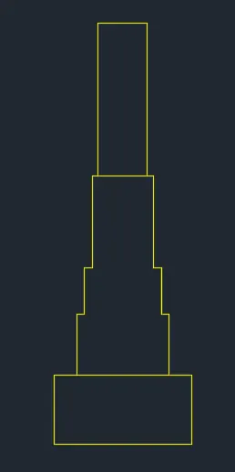
4.C-4
AIM:-
To create C.S of load bearing wall showing foundation details using Auto Cad.
Step by step procedure :-
- Command: UNITS
- Command: LIMITS
- Specify lower left corner (0,0)
- Specify upper right corner (420,297)
- Command: ZOOM
- Command: ALL
- Regenerating model
- Command: XLINE
- Specify a point: V
- Specify through point:
- Specify through point: cancel
- Command: offset
- Specify offset distance: T
- Select object to offset:
- Specify through point: 0.45
- Select object to offset:
- Specify through point: 0.45
- Select object to offset:
- Specify through point: 0.3
- Select object to offset:
- Specify through point: 0.3
- Select object to offset:
- Specify through point: 0.25
- Select object to offset:
- Specify through point: 0.25
- Select object to offset:
- Specify through point: 0.2
- Select object to offset:
- Specify through point: 0.2
- Select object to offset:
- Specify through point: 0.15
- Select object to offset:
- Specify through point: 0.15
- Select object to offset: Exit
- Command:XLINE
- Specify a point: H
- Specify through point:
- Specify through point: cancel
- Command: offset
- Specify offset distance: T
- Select object to offset:
- Specify through point: 0.45
- Select object to offset:
- Specify through point: 0.4
- Select object to offset:
- Specify through point: 0.3
- Select object to offset:
- Specify through point: 0.6
- Select object to offset:
- Specify through point: 1
- Select object to offset: Exit
- Command: TRIM
- Select Cutting edges
- Select object :Select All
- Trim and Erase all the extra lines
Result:
5.C-5
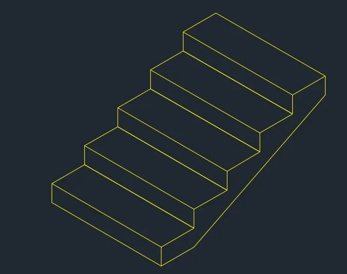
AIM:-
To create Isometric view of steps using Auto Cad.
Step by step procedure :-
- Command: UNITS
- Command: LIMITS
- Specify lower left corner (0,0)
- Specify upper right corner (420,297)
- Command: ZOOM
- Command: ALL
- Regenerating model
- Command: Isodraft
- Enter an option < orthographic >: Left
- Command: Line
- Specify first point :
- Specify next point :0.15
- Specify next point :1
- Specify next point :0.15
- Specify next point :Close
- Command:
- Command: Line
- Specify first point:
- Specify next point:0.30
- Specify next point:1
- Specify next point:0.3
- Exit
- Command:COPY
- Select object
- Specify base point
- Specify second point:
- Specify second point:
- Specify second point:
- Specify second point:
- Specify second point:
- Specify second point:Exit
- Command:
- Command:LINE
- Specify first point:
- Specify next point:0.15
- Specify next point:
- Command:
- Command:LINE
- Specify first point:
- Specify next point:0.3
- Specify next point:
- Command:LINE
- Specify first point:
- Specify next point:
- Exit
Result:
6.C-6
AIM:-
To create Isometric view of Gable wall using Auto Cad.
Step by step procedure :-
- Command: UNITS
- Command: LIMITS
- Specify lower left corner (0,0)
- Specify upper right corner (420,297)
- Command: ZOOM
- Command: ALL
- Regenerating model
- Command: Isodraft
- Enter an option < orthographic >: Left
- Command: Line
- Specify All the points
Result: