Creating a Floor plan, Footing detail and Isometric view using AutoCad
1.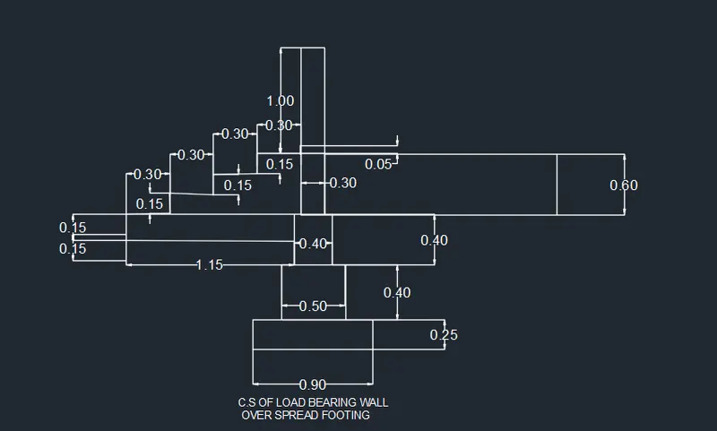
1.first i am setting the drawing limits command for xy dimensions(0,0) enter (100,100) for lower and upper limits.
2.and i used rectangular and line command for steps of footing
3.after i used offset command for to set steps of footings both side equal offsets
4.i used dimension line linear for to measure the dimension
5.in dimension command i changed the settings text height and arrow size for to visible in drawing sheet
6.and i used multitextline for to write the title of this drawings.
7.and i used trim,extend command lines also where it is required.
8.and i used snap cursors,snap grid ,polar trackings, cursor to specified angles in drawing sheet.and display drawing grids on
2.
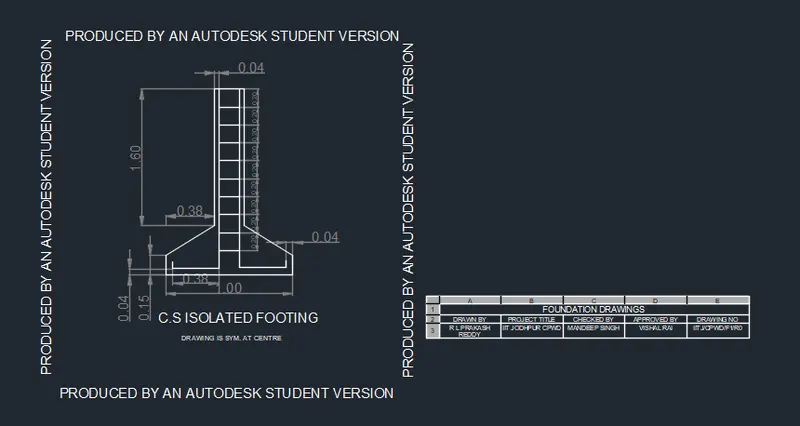
1.first i am setting the drawing limits command for xy dimensions(0,0) enter (100,100) for lower and upper limits.
2.and i used rectangular and line command for steps of footing
3.after i used offset command for to set the reieforcement stirrups for to show with equal offsets
4.i used dimension line linear for to measure the dimension
5.in dimension command and i changed the settings text height and arrow size for to visible in drawing sheet
6.and i used multitextline for to write the title of this drawings.
7.and i used trim,extend command lines also where it is required.
8.and i used rotate command also to rotate the side text box for four sides.
9. and i also used extra title table command to give the details.
10.and i used snap cursors,snap grid ,polar trackings, cursor to specified angles in drawing sheet.and display drawing grids on
3.
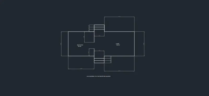
1.first i am setting the drawing limits command for xy dimensions(0,0) enter (100,100) for lower and upper limits.
2.and i used rectangular and line command for steps of footing
3.after i used offset command for to set steps at entrance area with both side equal offsets
4.i used dimension line linear for to measure the dimension
5.in dimension command i changed the settings text height and arrow size for to visible in drawing sheet
6.and i used multitextline for to write the title of this drawings.
7.and i used trim,extend command lines also where it is required. trim means to cut the line inbetween the two lines.
8.and i used snap cursors,snap grid ,polar trackings, cursor to specified angles in drawing sheet.and display drawing grids on
4.
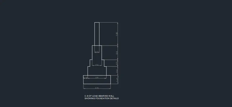
1.first i am setting the drawing limits command for xy dimensions(0,0) enter (100,100) for lower and upper limits.
2.and i used rectangular and line command for steps of footing
3.after i used offset command for to set steps of footings both side equal offsets
4.i used dimension line linear for to measure the dimensions
5.in dimension command i changed the settings text height and arrow size for to visible in drawing sheet
6.and i used multitextline for to write the title of this drawings.
7.and i used trim,extend command lines also where it is required. trim means to cut the line inbetween the two lines.
8.and i used snap cursors,snap grid ,polar trackings, cursor to specified angles in drawing sheet.and display drawing grids on
5.
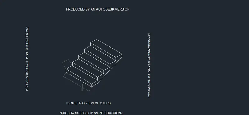
1.first i am setting the drawing limits command for xy dimensions(0,0) enter (100,100) for lower and upper limits.
1a.and i am used the DS settings for isometric snap to draw the lines in isometric views.
2.and i used rectangular and line command for steps of footing
3.after i used offset command for to set steps of footings both side equal offsets
4.i used dimension line linear and angular for to measure the dimension
5.in dimension command i changed the settings text height and arrow size for to visible in drawing sheet
6.and i used multitextline for to write the title of this drawings.
7.and i used trim,extend command lines also where it is required.
8.and i used snap cursors,snap grid ,polar trackings, cursor to specified angles in drawing sheet.and display drawing grids on
6.
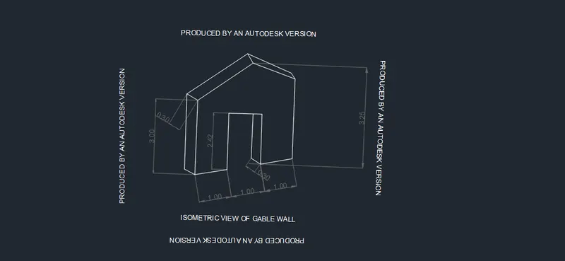
1.first i am setting the drawing limits command for xy dimensions(0,0) enter (100,100) for lower and upper limits.
1a.and i am used the DS settings for isometric snap to draw the lines in isometric views.
2.and i used rectangular and line command for steps of footing
3.after i used offset command for to set steps of footings both side equal offsets
4.i used dimension line linear and angular for to measure the dimension
5.in dimension command i changed the settings text height and arrow size for to visible in drawing sheet
6.and i used multitextline for to write the title of this drawings.
7.and i used trim,extend command lines also where it is required.
8.and i used snap cursors,snap grid ,polar trackings, cursor to specified angles in drawing sheet.and display drawing grids on