Creating a Floor plan, Footing detail and Isometric view using AutoCad
AIM: To create floor plan,footing details and isometric view using autocad
cammand used:
- line
- offset
- rectangle
- snap mode
- orthomode
procedure:
C1. cross section of load bearing wall over spread footing:
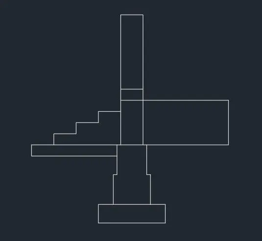
- choose the line cammand and specify the first point (0.9)
- specyfy the next point (@0,0.25) (@-0.2,0) (@0,0.4) (@-0.05,0) (@0,0.4) (@-0.05,0) (@0,1.75) (@-0.3,0) (@0,-1.75) (@-0.05,0)
- From point (-0.3,0) specify the offset distance 1,and specify next offset distance 0.15 and specify next point (@0.15,0) (@0,-0.6) (@-1.3,0)
- From the point (0.15,0) choose the next point (@0,-0.15) (@-0.3,0) (@,-0.150) (@-0.3,0) (@0,-0.15) (@-0.3,0) (@0,-0.15) (@-0.3,0) (@0,-0.15) (1.15,0) (@0,-0.25) (-0.05,0) (@0,-0.4) (@-0.2,0) (@0,-0.25)
- from point (@0,-0.25) choose the next point (@0,0.15) (@-0.85,0)
c2:Cross section of isolated footing:
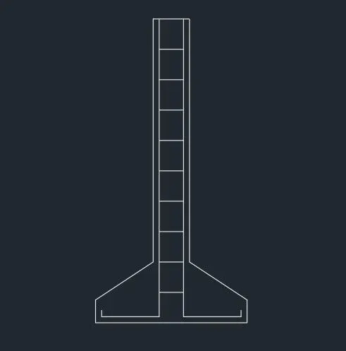
- Choose the line cammand specify the point (@0,-0.04) (@0.38,0) (@0,2) (@0.16,0) (@0,-2) (0.38,0) (0,0.04)
- From point (@0.16,0) specify the next point (@-0.04,0) (@0,-1.6) (@-0.38,0) (@0,-0.25) to join the line trim the extra line (@0,-0.15) (@1,0) (@0,0.15) (@0,0.25) (@-0.38,0) to join line trim the extra line and specify next point (@0,1.6) (@-0.04,0)
3.Line diagram of two bedroom building:
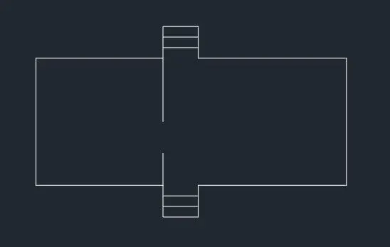
- choose the line cammand and specify the point (@0,-3.6) (@0,-3.6) (@0,3.6) (@0,-0.9) (@1,0) (@0,0.9) (@4.2,0) (@0,3.6) (@-4.2,0) (@0,-0.9) (@-1,0) (@0,-0.9) (@0,-1.8)
- From the point (@0,3.6) specify the next point (@0,0.9)
- From the point (@0,-0.9) specify the offset diastance 0.3 simularly,0.3,0.3
4.Cross section of load bearing wall showing foundation details:
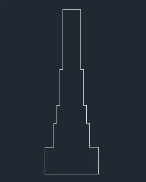
- choose the line cammand specify the distance (0.9,0)
- Specify the next point (@0,0.45) (@-0.15,0) (@0,0.4) (@-0.05,0) (@0,0.3) (@0.05,0) (@0,0.6) (@-0.05,0) (@-0.3,0)
- From the point (0.9,0) specify the next point (@0,0.15) (@0.05,0) (@0,0.4) (@0.05,0) (@0,0.3) (@0.05,0) (@0,0.6) (0.05,0) (@0,1)
- From the point (@0.15,0) specify the next piont (0.6,0)
Isometric view of steps:
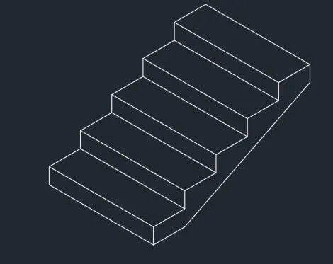
- Firstly on the isometric view and choose the line cammand specify the diatance 0.15 and specify drection isoplain top
- Then isoplain right 0.3, isoplain top 0.15 ,isoplain right 0.3, isoplain top 0.15, isoplain right 0.3, isoplain top 0.15, isoplain right 0.3, isoplain 0.15 and isoplain right 0.3
- From the point 0.15 specify next point isoplain left 1 and simularly above steps
- From the point 0.15 isoplain right 0.3
- From the top point isoplain down direction 0.15 and join the direction of line
6.Isometric view of gable wall:
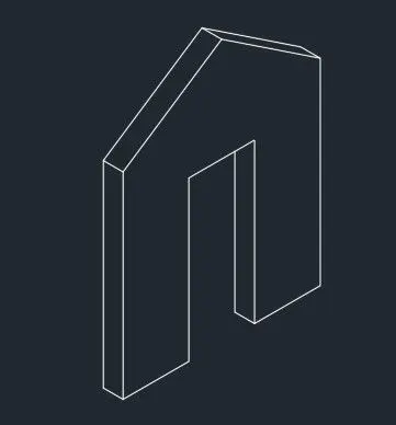
- choose the isometric view and specify the line cammand and specify the diance 3 isoplain top
- and isoplain left 0.3, isoplain down the direction 3,isoplain right 0.3, isoplain right 1, isoplain top 2.42,isoplain right 1,isoplain down direction 2.42, isoplain 1 isoplain top 3
- From the point 3 isoplain left 1.5,isoplain top 4 and join the required direction of line
Result:
Created a floor plan,footing details and isometric view using Auto Cad had good understanding about variuos cammand in auto cad