Creating 3D Isometric view of various structural elements in AutoCAD
AIM:
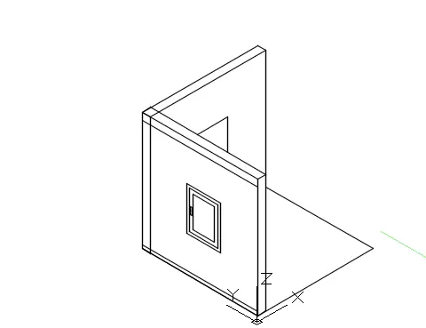
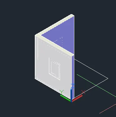
1. Create a 3D Isometric View of the building with plan and elevation given.
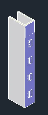
2. Create the 3D View of the Building Façade as given in the plan and elevation. Also, see the detail of the window.
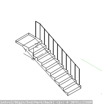
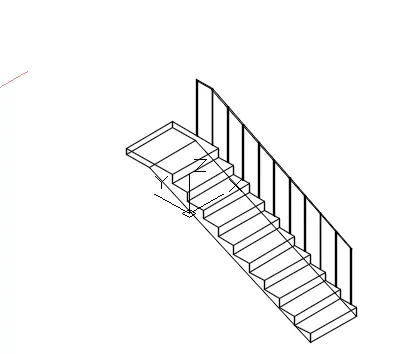
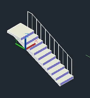
3. Create the ismoteric 3d view of a stair with railing as shown in the plan and elevation. Assume the size of the balustrades and the hand rails.
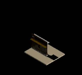
4. Create the 3D view of a Wall with spread footing . Create the Door opening only. Assume the size of the parpaet and the coping. See the plans and elevation for the details. Also, create a rendered view of the model with materials as of your choice.
PROCEDURE:
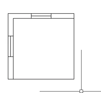
1. Open a drawing select 3D modeling and select units engineering. then go to the top view and draw the plan of the buiding .draw aline of size 10'9" in -x direction and other with it towards negative yof size 10'9".them offset both the lines with 9" and join all the corner points. and then draw the window by offset in -x direction by 3'6" and then 3' and again offset 3'5" in y direction and then 3'2" in y direction
then go to the WCS view give command ucs and select the xdirection in the direction of wall and xy plane in the direction of the height of the wall first we draw the B elevation by .
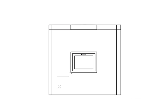
give command rec then select the corner point of the plan as the first point and other point as @10'9",11' then explode the rectangle and give offset command select distance 4" and select the bottom line similarly give offset select the top line and give offset 6"
and then draw the window give offset 3' and then 4' and then draw lines from the plan in the wall and then trim the unwanted line
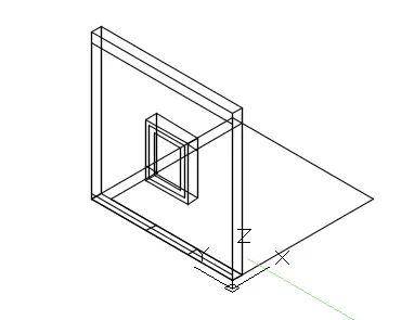
now give the region command and select the all the lines of the rectangle draw in the first and the window then give extrude command select mode solid and give distance 9"
then go to the WCS view give command ucs and select the xdirection in the direction of wall and xy plane in the direction of the height of the wall first we draw the B elevation by .
give command rec then select the corner point of the plan as the first point and other point as @10'9",11' then explode the rectangle and give offset command select distance 4" and select the bottom line similarly give offset select the top line and give offset 6"
and then draw the window give offset 3' and then 4' and then draw lines from the plan in the wall and then trim the unwanted line
now give the region command and select the all the lines of the rectangle draw in the first and the window then give extrude command select mode solid and give distance 9"
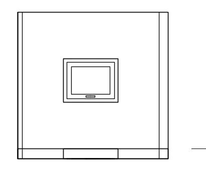
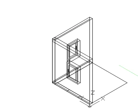
2.Open a drawing select 3D modeling and select units engineering. then go to the top view and draw the plan of the buiding . then give commadnd rectangle and draw arectangle of @6'10",10'9"
then explode the rec and offset from from bottom and bot ends 9" then draw the window at the bottom of the plan of 3' frpm 1'11" dist.
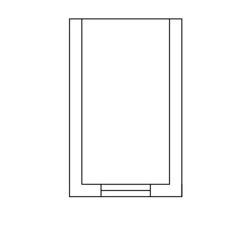
then selec the wall area and make it a region by region command then extrude it and give the height as the height of the building or elevation count it from the figure which is 47'3".
Then give the ucs command make the wall area as working plane now select the top view and draw a line in all the places where window is to be placed from the bottom of the wall by referring in the plan to the top of the wall then draw aline at the front elevation in the bottom and offset it on all the areas where the window is to be placed .
then in the same view draw the window by rectangle command specify first corner anywhere and other corner as @3',4' then offset it by 2" and explode the rectangle and from midpoint of top line draw a line and then join both the rectangles and then offset both again by 3" .
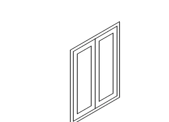
now copy the windows pick base point as the top corner left and place it in all the area as required per the plan and then erase all the reference line drawn to place windows.
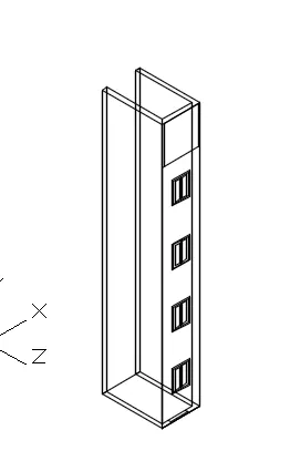
3.
.Open a drawing select 3D modeling and select units engineering. then go to the right view then
Command:
Command: _line
Specify first point:
Specify next point or [Undo]: 3'
Specify next point or [Undo]: @0,0,-6"
Specify next point or [Close/Undo]: 1'
Specify next point or [Close/Undo]: *Cancel*
then copy the stairs
Command: _copy 2 found
Current settings: Copy mode = Multiple
Specify base point or [Displacement/mOde] :
Specify second point or [Array] : A
Enter number of items to array: 9
Specify second point or [Fit]:
Specify second point or [Array/Exit/Undo] : *Cancel*
Command: l
LINE
Specify first point:
Specify next point or [Undo]: @0,0,-6"
Specify next point or [Undo]: *Cancel*
Command: l
LINE
Specify first point:
Specify next point or [Undo]: @0,0,-4"
Specify next point or [Undo]: 1'6"
Specify next point or [Close/Undo]:
Specify next point or [Close/Undo]: *Cancel*
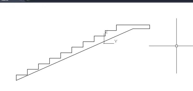
go to the wcs view
then make it aregion and extrude it to 3'(assumed)
Command: REGION
Select objects: Specify opposite corner: 23 found
Select objects:
1 loop extracted.
1 Region created.
Command:
Command:
Command: _extrude
Current wire frame density: ISOLINES=4, Closed profiles creation mode = Solid
Select objects to extrude or [MOde]: _MO Closed profiles creation mode [SOlid/SUrface] : _SO
Select objects to extrude or [MOde]: 1 found
Select objects to extrude or [MOde]:
Specify height of extrusion or [Direction/Path/Taper angle/Expression]: 3'
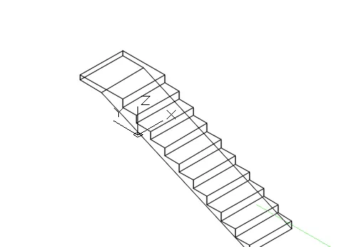
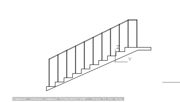
Then draw rhe handle care in the right elevation
Command: _line
Specify first point:
Specify next point or [Undo]: @0,0,3'2"
Specify next point or [Undo]: *Cancel*
then copy the line and array 11.
4.
4. first draw the cross section of the footing. give the ucs command select the x direction and xy plane according to the required direction. then give the line command and start drawing the footing using line and offset command and then create all theregions using boundary command .
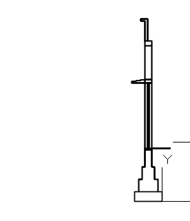
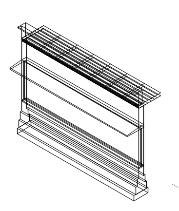
then go to the ucs view and extrude the regions by -7500
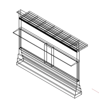
then go to the ucs view select the ucs to work in the wall area go to top view and create a door opening of height 2100 and width 900 and extrude it 300 mm.
now create the rendered view of the model. first give colurs to the walls and projection and door
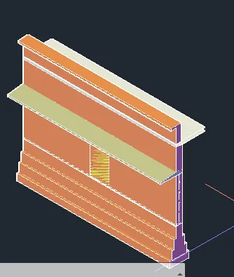
then create the a box at the plinth level and draw a cylinder to place the camera .
give the height of the cylinder as where to place the camera then give cam view command select the dtarget and lens size as 25mm name the camera view as 1.
then go to the lights select distant light and place it and select the direction if the light and the target .
then go to the rmat select different materials for walls door and footing and projection and then assign it to them .
then give the command RR and see the rendered view.
RESULT:
1.
2.
3.
4.