Creating 3D Isometric view of various structural elements in AutoCAD
Aim - To create a 3d isometric view of given plan and elevation
Procedure-
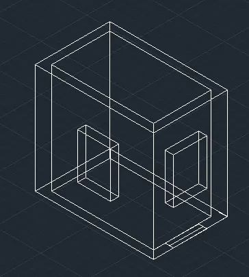
Firstly invoke 3d modelling or basics
Then in the top view draw the 2d plan
Create a boundary ising BOUNDARY command
Create a region using REGION command
Then go to isometric view
Then presspull or extrude the plan to 10' in Z axis
Then Draw the windows
Create a rectangle then region
Then shaded view
Then union it
MOVE a rectangle to Z axis at distance
Then extrude it to 4'
In the both the directions
2.
Aim - To create a 3d isometric view of given plan and elevation
Procedure-
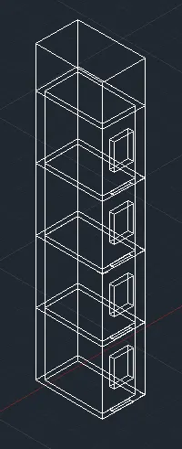
Then in the top view draw the 2d plan
Create a boundary ising BOUNDARY command
Create a region using REGION command
Then go to isometric view
Then presspull or extrude the plan to 10' in Z axis
Then Draw the windows
Create a rectangle then region
Then shaded view
Then union it
MOVE a rectangle to Z axis at distance
Then extrude it to 4'
Copy and paste to all four floors in the isometric view
In the final floor dont keep windows
3.
Aim - To create a 3d isometric view of given staircase
Procedure-
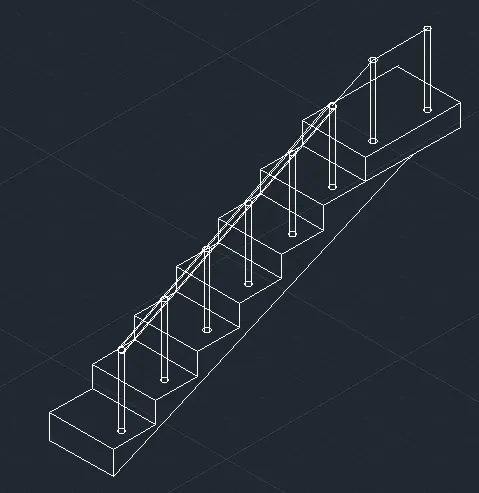
IN the isometric view
Draw stairs riser of 6" and platform of 1'
Copy paste to all the steps
Then extrude the thread to 3'
Then draw the railing
Draw the circle and extrude
Copy paste to all the stairs
Then draw the line
Then give path of railing
Aim - To create a 3d isometric view of given section of wall
Procedure-
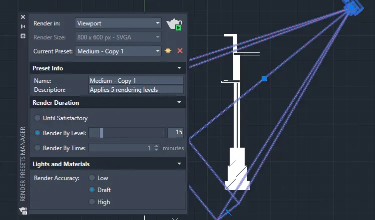
Draw the section in the 2d view
Using REC command and line command
In the visualize tab
Set the camera and point and lens
Set a spot light
Give point light
Then start rendering using RR command
It is displayed in the window