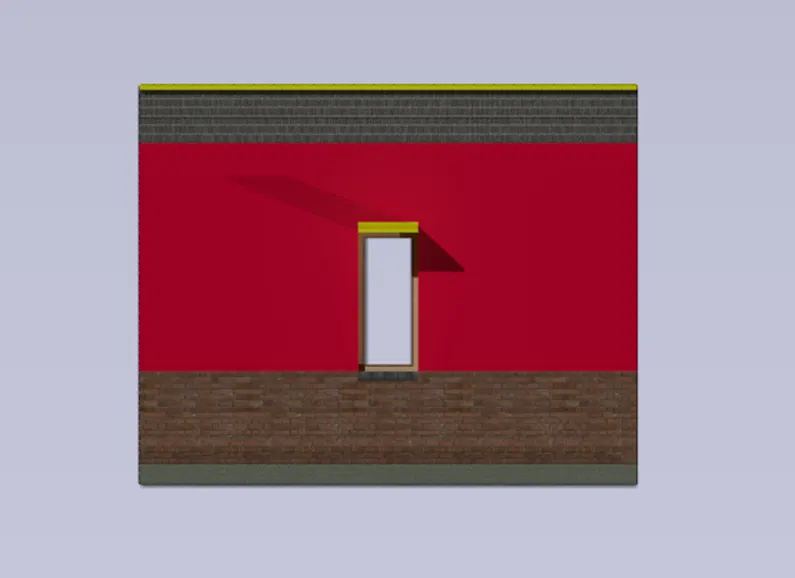
Creating 3D Isometric view of various structural elements in AutoCAD
- Create a 3D Isometric View of the building with plan and elevation given.
Aim: To create a 3D isometric View of the building using AutoCAD software.
Introduction:
Various commands used
- QNEW command
- UN command
- LIMAX command
- Zoom command
- Box command
- Polysolid command
- EXTRUDE command
- SUB command
- Move command
- REC command
- UNION command
- Region command
Procedure:
- Type QNEW in command box, press enter, select the default setting as imperial and select ok.
- Type UN in command box, press enter, select the unit of measurement as engineering with the precision 0’0”.
- Type limax in command box, press enter, specify max limit as 20’,20’ and press enter.
- Type Z in command box, press enter, type Ain command box, press enter.
- Select the 3D modelling option from status bar from setting.
- Type BOX in command box, press enter, select the length option from command box, specify length as 10’9” press enter, specify width as 10’9”, press enter, specify height as 4” and press enter.
- Type POLYSOILD in command box, press enter, select width option from command box, specify width as 9” press enter, select the height option from command box, specify height as 10’ and press enter, select the justify option from command box, and specify justification as left.
- Specify start point of polysoild, specify next point as 10’9” press enter, and specify next point as 10’4.5” and press enter twice.
- For drawing the window, type REC in command box, press enter, draw the rectangle of size 3’2”x9” in middle portion of wall.
- Type REGION in command box, press enter, select the just drawn rectangle and press enter.
- Type EXTRUDE in command box, press enter, specify height of extrusion as 4’ and press enter.
- Type MOVE in command box, press enter select just drawn box and specify next point as @0,3’,0 and press enter.
- Select the view as 2D wireframe view from viewport control.
- Type SUB in command box, press enter, select the polysoild wall, press enter, select the moved box, and press enter to create the window opening.
- Outside the drawing, type BOX in command, press enter, select the length option from command box, specify length as 3’2” press enter, specify width as 3”, press enter, specify height as 4’ and press enter.
- Again, type BOX in command, press enter, specify first point, select the length option from command box, specify length as 32” press enter, specify width as 3”, press enter, specify height as 42” and press enter.
- Type MOVE in command box, press enter, select the just drawn box, press enter, specify base point as midpoint of width and specify second point as @3,3,0 and press enter.
- Type SUB in command box, press enter, select the external box, press enter, select the internal box, and press enter.
- Similarly draw the internal frame of window of 4” thickness.
- Type REC in command box, press enter, select the first point as midpoint of inner box, select the dimension option from command box, specify length as 24 and width as 34 and press enter.
- Type region in command box, press enter, select the just drawn rectangle to create it as surface.
- type UNION in command box, press enter, select the entire window parts and press enter to create it as a single unit.
- Type MOVE in command box, press enter, select the entire window and move it to the window opening of wall.
- Similarly create the second window of 3’ length.
- From the material panel of visualization tab select the material browser and select the flooring type as floral, add it to the list, select the flooring, right click on the floral option from list and select assign to selection option to apply flooring material.
- Select the material mapping from the material panel of visualization tab and adjust the applied material
- Similarly apply the material to the wall as wall painting material and apply glass inside the window as clear yellow glass material,
Result:
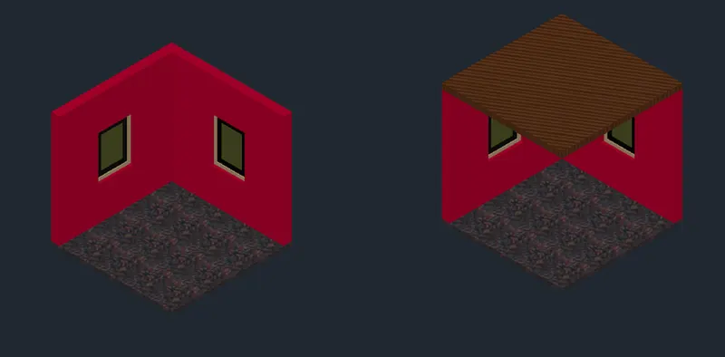
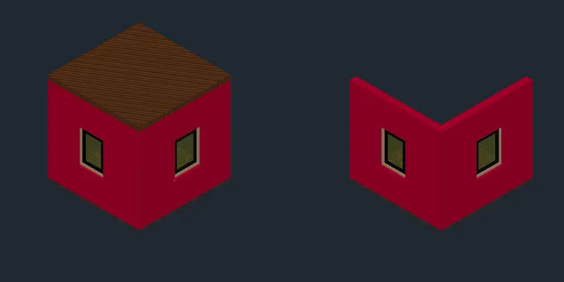
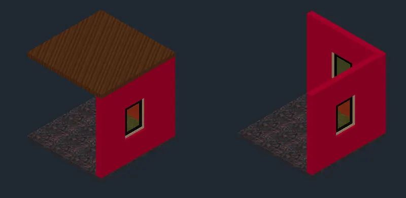
3D Isometric View of the building is created using AutoCAD software by following the above-mentioned procedure as shown below.
SW View with or without roofing
NE View with or without roofing
SE view with or without roofing
- Create the 3D View of the Building Façade as given in the plan and elevation. Also, see the detail of the window.
Aim: To create 3D View of the building Façade using AutoCAD software.
Introduction:
Various commands used
- QNEW command
- UN command
- LIMAX command
- Zoom command
- Trim command
- Plan command
- Region command
- Extrude command
- Line command
- Rectangle command
- Move command
- SUB command
- Box command
- Union command
- Copy command
- POLYSOILD command
Procedure:
- Type QNEW in command box, press enter, select the default setting as imperial and select ok.
- Type UN in command box, press enter, select the unit of measurement as engineering with the precision 0’0”.
- Type limax in command box, press enter, specify max limit as 20’,20’ and press enter.
- Type Z in command box, press enter, type Ain command box, press enter.
- Select the 3D modelling option from status bar from setting.
- Select the top view from viewport control.
- Type offset in command box, specify offset distance as 9”, press enter and take offset inside the rectangle.
- Type tr in command box, press enter
- Type 3P in command box, press enter, specify first point on screen, specify next point as @0,10’9”,0, press enter, specify next point as @9”,0,0, press enter, specify next point as @0,-10’,0, press enter, specify next point as @1’2”,0,0 press enter, specify next point as @0,-9,0 , press enter and select the close option from command box.
- Type rec in command box, press enter, specify first corner point at top right corner of polyline, select the dimension option from command box, specify length as 3’ and width as 9” and press enter.
- Type MIR in command box, press enter, select the polyline, select the first point on mirror line at bottom midpoint of rectangle and second point on mirror line as top midpoint of rectangle.
- Change the view to SW from viewport control.
- Type region in command box, press enter, select the two drawn polylines and press enter.
- Type EXTRUDE in command box, press enter, select the two polylines and specify height as 41’3” with taper angle 0 and press enter.
- Again, type EXTRUDE in command box, press enter, select the rectangle drawn at window opening and specify extrusion height as 4’6” and press enter.
- Type rec in command box, press enter, specify corners on top of just extruded box.
- Type MOVE in command box, press enter, select the just drawn rectangle, specify base point as corner of rectangle and specify next point as @0,4’2”,0 and press enter.
- Type extrudes in command box, press enter, select the rectangle and specify height as 5’11” and press enter.
- Similarly create the upper window opening.
- For creating the window, type BOX in command box, press enter, select the length option from command box, specify length as 3’, width as 2” and height as 4’ and press enter.
- Again, type box in command box, press enter, specify first point at corner of above box, select length option from command box, specify length as 32”, width as 44” and height as 2” and press enter.
- Type MOVE in command box, press enter, select the just drawn box, select the base as midpoint of box edge and specify next point as @3,3,0 and press enter.
- Type SUB in command box, press enter, select the outside box, press enter, select the inside box and press enter it will create opening inside the frame.
- Type BOX in command box, press enter, select the first point as corner of opening, select the length option from command box, specify length as 17”, width as 1” and height as 44” and press enter.
- Similarly create the box of length 11”, width 38” and height 1” by specifying the same point as first point and move it to appropriate position such that it is at midpoint of opening.
- Type SUB in command box, press enter, select the outside box, press enter, select the inside box and press enter it will create opening inside the glass frame.
- Type rec in command box, press enter, and draw the rectangle inside the opening.
- Type region in command box, press enter, select the just drawn rectangle to create it as the surface.
- Type CO in command box, press enter, select the just drawn portion of frame and copy it to create another panel of window.
- From the material panel of visualization tab select the material browser and select the wood material in that material type as white oak and add it to the list, select the frame of window, right click on the selected wood option from list and select assign to selection option to apply wood material.
- Select the material mapping from the material panel of visualization tab and adjust the applied material
- Similarly apply the material to the window as metal aluminum painted white material and apply glass inside the window as blue glass material,
- Type UNION in command box, press enter, select the all-window components and press enter to create it as single unit.
- Type CO in command box, press enter, select the window and copy it to midpoint of opening for creating window of 4’ height.
- Similarly create window of height 4’2” and place it to required position.
- Type polysoild in command box, press enter, select width option and specify it 4”, select height from command box, specify it as 9” and press enter, select justify option and specify left justification, specify first point as right bottom corner, next point as @6’5”,0,0 press enter, next point as @0,0,6’5” press enter, and last point as @-6’7”,0,0 and press enter.
- Select the wall face and assign it color using property option by right clicking.
Result:
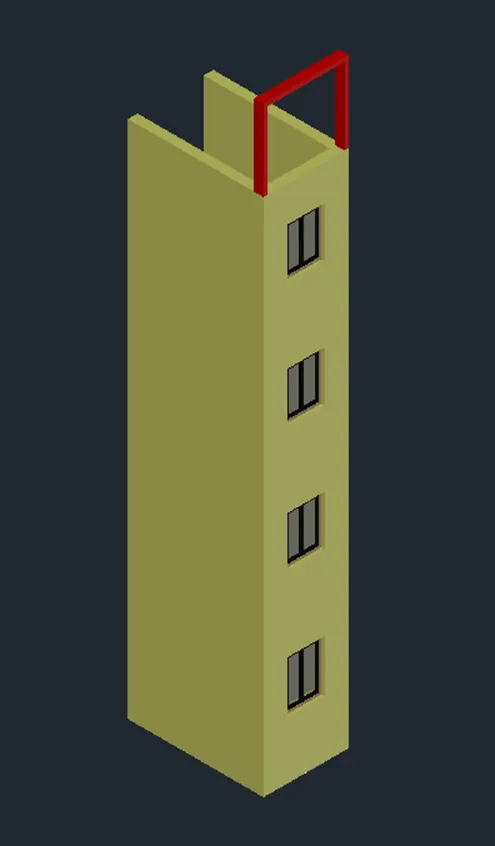
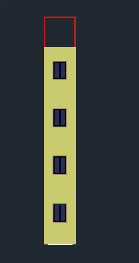
3D view of building façade is created in AutoCAD software by using the above-mentioned procedure as shown below.
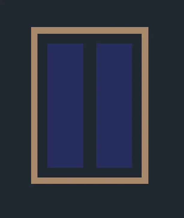
Front view of window
SW view
Front view
- Create the isometric 3d view of a stair with railing as shown in the plan and elevation. Assume the size of the balustrades and the hand rails.
Aim: To create the isometric 3d view of a stair with railing using AutoCAD software.
introduction:
Various commands used
- QNEW command
- UN command
- LIMAX command
- Zoom command
- Box command
- CO command
- 3P command
- EXTRUDE command
- Union command
- Cylinder command
- Sweep command
Procedure:
- Type QNEW in command box, press enter, select the default setting as imperial and select ok.
- Type UN in command box, press enter, select the unit of measurement as engineering with the precision 0’0”.
- Type limax in command box, press enter, specify max limit as 20’,20’ and press enter.
- Type Z in command box, press enter, type Ain command box, press enter.
- Select the 3D modelling option from status bar from setting.
- Type BOX in command box, press enter, select the length option from command box, specify length as 1’ press enter, specify width as 3’, press enter, specify height as 6” and press enter.
- Type CO in command box, press enter, select the box, press enter, specify base point as bottom of step and copy it to create the upper steps.
- Again, type box, in command box, press enter, specify base point as top endpoint of last step and select the length option from command box, specify length as 2’ press enter, specify width as 3’, press enter, specify height as 4” and press enter.
- Type 3P in command box, press enter, and create the waist slab of staircase.
- Type region in command box, press enter, select the just created 3d polyline and press enter.
- Type EXTRUDE in command box, press enter, select the 3D polyline and specify height as 3’ and press enter.
- Type cylinder in command box, specify center point, specify radius as 1.2”, press enter, specify height as 3’2” and press enter.
- Type CO in command box, press enter select the base point of cylinder and copy it to the upper steps at the required position.
- Type PL in command box, press enter and draw the polyline joining the top of all the cylinders.
- Draw the circle using circle tool.
- Type SWEEP in command box, press enter, select the object as the circle and select the path as polyline to seep and create the handrail.
- Select all the cylinders as balusters and handrail part and copy it to the other side of staircase.
- From the material panel of visualization tab select the material browser and select the flooring type as mosaic brown and apply it to the steps.
- Select the material mapping from the material panel of visualize tab and adjust the applied material.
- Similarly select the handrail and railing material from metal option add to the list, select the handrail and baluster part and assign the selected material to it.
- Type UNION in command box, press enter, select all the staircase and press enter to create it as a single unit.
Result:
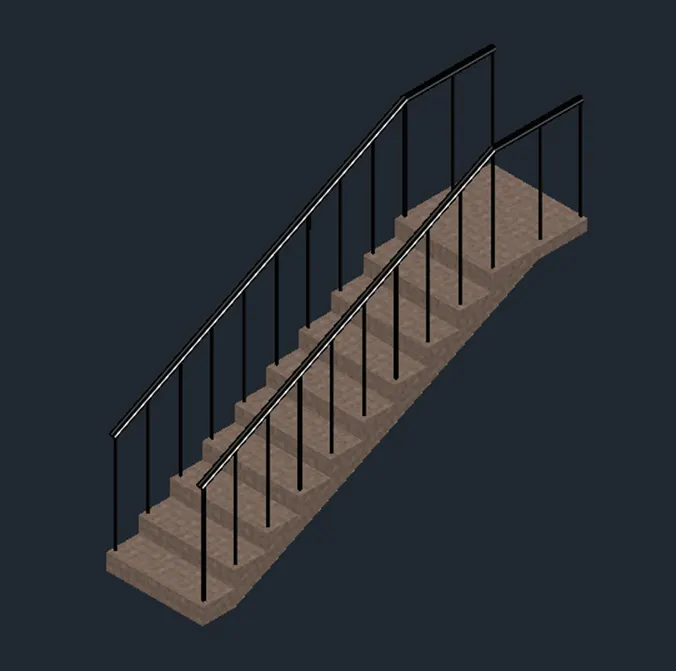
SW Isometric 3d view of staircase with railing is created using AutoCAD Software as shown below.
- Create the 3D view of a Wall with spread footing. Create the Door opening only. Assume the size of the parapet and the coping. See the plans and elevation for the details. Also, create a rendered view of the model with materials as of your choice.
Aim: To create 3D view of a wall with spread footing with rendered view of the model by applying materials to it using AutoCAD software.
Introduction:
Various commands used
- QNEW command
- UN command
- Limax command
- Zoom command
- Rec command
- 3P command
- Region command
- Extrude command
- Sub command
- Box command
- RR command
Procedure:
- Type QNEW in command box, press enter, select the default setting as metric and select ok.
- Type UN in command box, press enter, select the unit of measurement as decimal with the precision 0.
- Type limax in command box, press enter, specify max limit as 10000,10000 and press enter.
- Type Z in command box, press enter, type Ain command box, press enter.
- Select the 3D modelling option from status bar from setting.
- Select the left view from viewport control.
- Type REC in command box, press enter, select dimension option from command box, specify length as 900 and width as 300 and press enter and draw the rectangle.
- Type 3P in command box, press enter, specify first point at distance of 200 from top corner of rectangle, specify next point as @0,400, @50,0 next point as @0,400, next point as @50,0, next point as @0,600, next point as @300,0, next point @0, -600, next point @50,0, next point @0,-400, next point @50,0, next point @50,0, next point @400,0 respectively and press enter after specifying each point.
- Type REC in command box, press enter specify first point as top left corner, select dimension option from command box, specify length 300 and width 3300 and press enter.
- again, create the rectangle of size 150 x 800 to create the parapet wall above the wall.
- Also create the copping of size 200 x 50 above the parapet wall.
- Similarly create upper portion of section using rectangle tool.
- Outside the drawing, type REC in command box, press enter, select dimension option from command box, specify length as 300 and width as 2100 and press enter.
- Using the polyline create the chhajja portion above the opening.
- Type region in command box, press enter, select the entire geometry and press enter to create it as a region.
- Type EXTRUDE in command box, press enter, select the entire geometry and specify height as 7500 units and press enter, it will create the wall of 7500 unit length.
- Similarly, extrude the opening by specifying extrusion height as 900 units.
- Select the SW view from viewport control.
- Type MOVE in command box, press enter, select the opening and move it to the midpoint of wall.
- Type SUB in command box, press enter, select the outside wall, press enter, select the inside opening and press enter, it will create the opening.
- From the material panel of visualization tab select the material browser and select the flooring from Autodesk library, select tile diamond red and add it to the list.
- Select the flooring unit and right click on the added diamond red option from command box, and select assign to selected option.
- Select the material mapping from the material panel of visualize tab, click on drop down, select the box and adjust the applied material as per requirement.
- Similarly, apply the material below wall as English brick from masonry option and adjust the view using material mapping.
- Similarly apply the wall painting as light red, concrete below the wall masonry, and material to parapet wall and adjust it using material mapping.
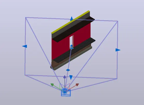
- From camera panel of visualize tab select create camera option and create the camera at certain height as shown below.
- Double click on camera, to see the camera view.
- Select camera and right click to change the properties of camera.
- From the render panel of visualize tab select the render in region option.
- Type RR in command box, press enter, pick the crop window to create the render.
- Similarly, create the different rendered view of cross section of wall with the footing.
- Select the render window option from the render drop down of render panel of visualize tab and save the view by selecting render in window option and save it.
Result:
3D view of wall opening is created in AutoCAD software using above mentioned procedure and various views as shown below.
Normal realistic view
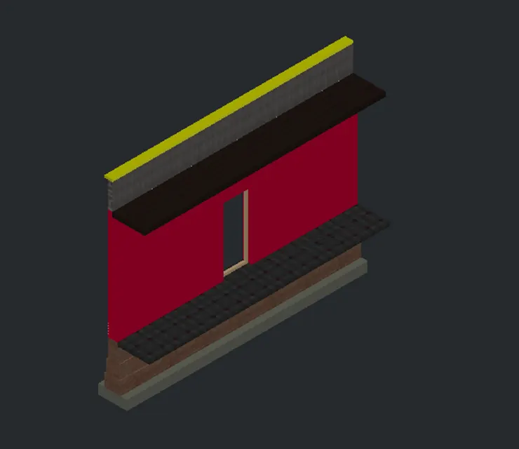
Camera view
Prespective view and parallel view
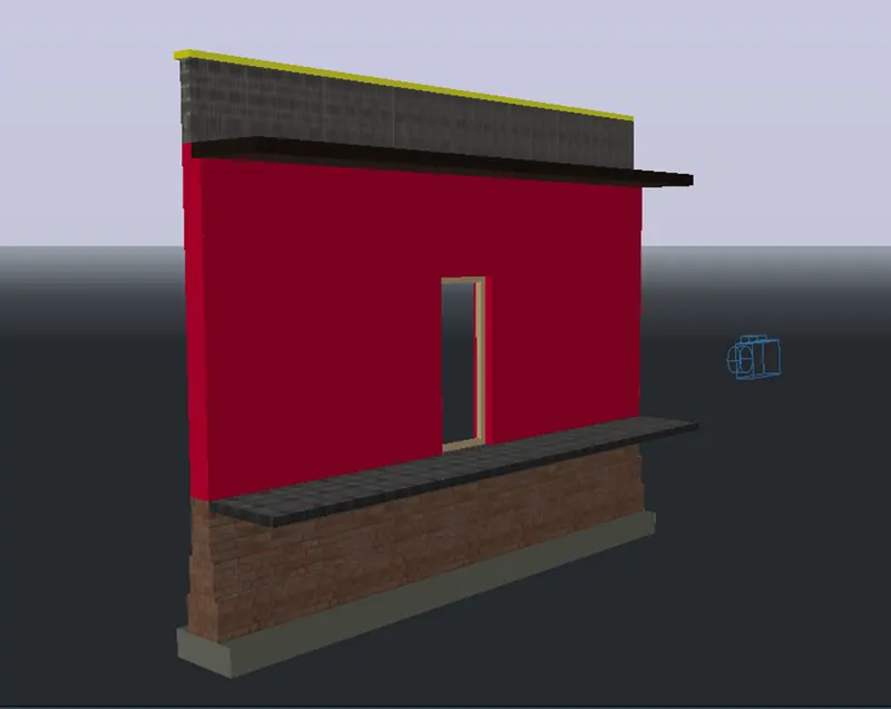
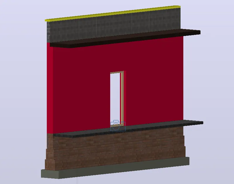
Rendered SW view
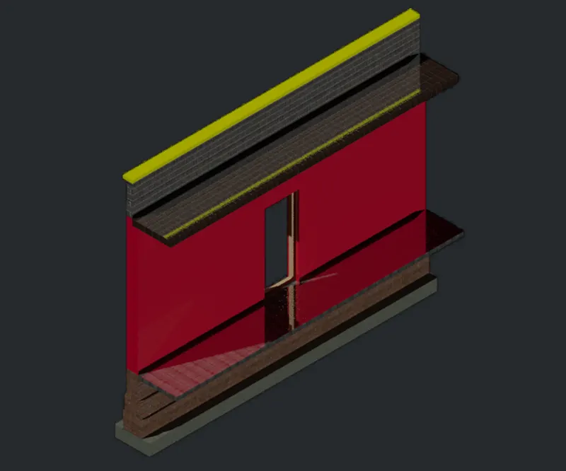
Rendered back view